Alpha HW110LC/TC Table Saws: Table Does Not Move After Removing Corner Bolts

Created by Gabriel Izzo, Modified on Fri, 22 May at 4:25 PM by Gabriel Izzo

Alpha HW110LC / HW110TC Table Saw · Setup & Alignment
Table Does Not Move After Removing Corner Bolts
Applicable Models
Alpha HW110LC (2HP)
Alpha HW110TC (3HP)
Table Saw Safety — Setup & Alignment
+
Unplug the table saw from power before performing any table alignment, adjustment, or maintenance. Never make alignment changes while the machine is connected to a power source.
+
Wear safety glasses when removing fasteners — small screws and set screws can eject unexpectedly under spring tension or thread load.
Overview — Cabinet-Mounted Table

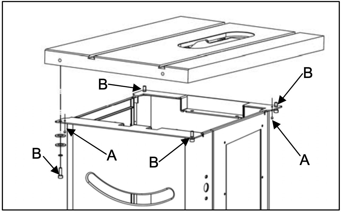
On the HW110LC and HW110TC table saws, the cast iron table is cabinet-mounted — the main portion of the table is secured directly to the cabinet using four cap screws (M10-1.5 x 25mm) at the corners.

Hidden Set Screws — Shipping Locks
In addition to the four corner cap screws, there are two set screws located diagonally at the front-left and rear-right corners of the table.
These set screws are positioned next to the mounting bolts and are typically concealed beneath the flat washers.
They are installed at the factory to prevent the table from shifting during shipping.
Important — Remove the Set Screws Completely

These set screws must be completely removed before attempting any alignment adjustments. As long as they remain in place, they will lock the table in position and prevent any movement — even after the four corner cap screws are removed.

Once removed, the set screws should be discarded — they are intended for shipping stability only and will not realign properly if reused.

Aligning the Table T-Slot Parallel with the Blade
Manual Reference — Section 6.2, Page 19
1
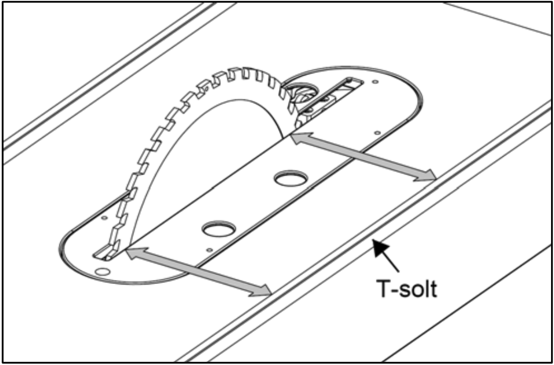
The table T-slot must be aligned parallel with the blade. Using a combination square, measure the distance from the back edge of the blade to the table T-slot. Pivot the blade forward 180° and re-measure the distance using the exact same point on the blade. The difference between both measurements must be less than 0.2 mm. Refer to Fig. 23.
2
If an adjustment is necessary, loosen the two M5-8x8 set screws (A) and four M10-1.75x25 cap screws (B) identified in Fig. 24 which mount the table to the cabinet. Make the needed adjustment until both measurements are equal or less than 0.2 mm, then re-tighten all the screws.
Fig. 23 — T-Slot Alignment Reference
Fig. 23 - T-slot alignment diagram
Fig. 24 — Set Screws (A) and Cap Screws (B) Location
Fig. 24 - Set screws A and cap screws B mounting diagram
Video Demonstration
HW110LC/TC — Removing the Shipping Set Screws
i

For further assistance with table alignment on your HW110LC or HW110TC, please contact our support team.

Was this article helpful?

That’s Great!

Thank you for your feedback

Sorry! We couldn't be helpful

Thank you for your feedback

Let us know how can we improve this article!

Select at least one of the reasons
CAPTCHA verification is required.

Feedback sent

We appreciate your effort and will try to fix the article