Shark S-10 Universal Overhead Guard: Installation on Traditional L-Type Rear Rails
Created by Gabriel Izzo, Modified on Tue, 30 Jun at 5:01 PM by Gabriel Izzo
This guide covers installing the Shark S-10 Universal Overhead Guard on traditional "L"-type rear rails that are not Harvey Big Eye rails. Before proceeding, confirm your rear rail profile matches the L-type configuration and that all installation dimensions meet the specifications in this guide.
If your saw is equipped with Harvey Big Eye rails, refer to the Big Eye-specific installation guide instead.
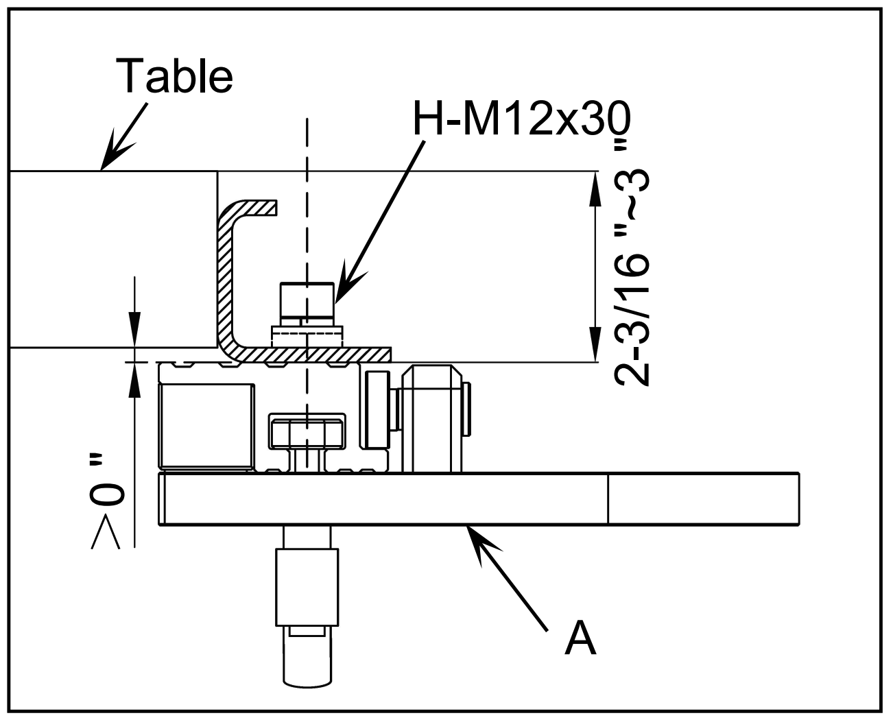
With the Shark S-10 in position, confirm the following before proceeding:
| Dimension / Check | Required Value |
|---|---|
| Table-to-rail clearance | > 0" — table surface must clear the top of the rear rail assembly |
| Mounting bolt spec | H-M12 × 30 |
| Rail vertical depth (point A) | 2-3/16" to 3" — measure from the table surface down to the mounting face of the L-rail |
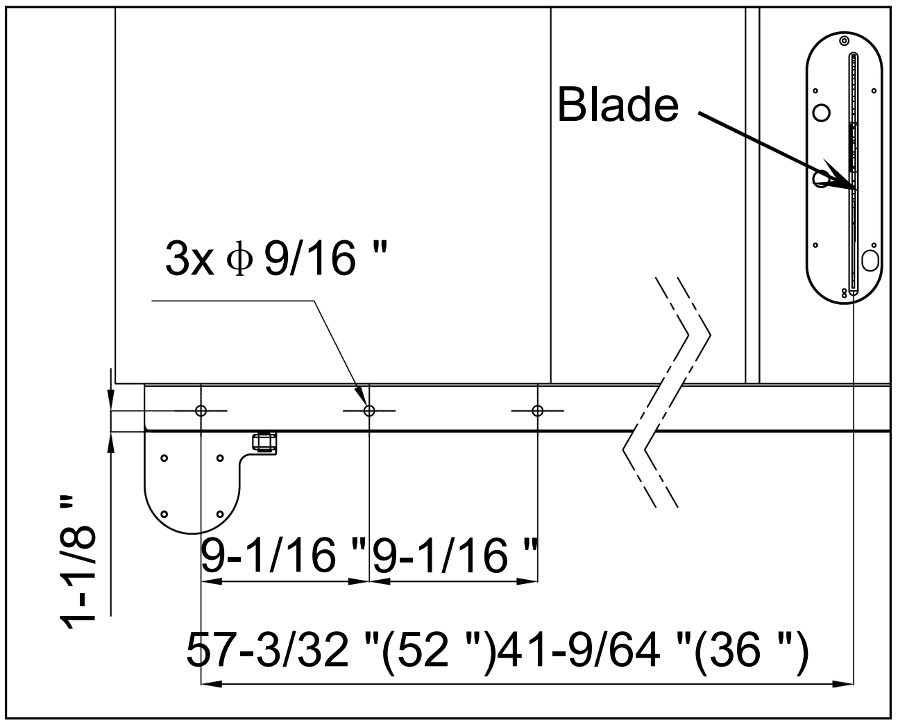
Using a centre punch and scribe, mark hole positions on the rear rail before drilling. Refer to the dimension reference below:
| Dimension | Value |
|---|---|
| Hole quantity and diameter | 3× Ø 9/16" |
| Width between hole center and outer edge of the rail | 1-1/8" |
| Hole spacing (center to center) | 9-1/16" | 9-1/16" |
| Total span — 52" fence rail | 57-3/32" |
| Total span — 36" fence rail | 41-9/64" |
Determine whether your fence rail is a 52" or 36" configuration and use the corresponding total span dimension (57-3/32" or 41-9/64") to position the three hole centers.
Measure 1-1/8" up from the base of the rear rail and mark a horizontal reference line. Along this line, mark the three hole centers at 9-1/16" intervals, starting from the leftmost hole position per Fig. 6. Use a centre punch to create a clear drill start point at each mark.
Using a 9/16" drill bit, drill all three holes at the marked positions. Keep the drill perpendicular to the rail face. Remove any burrs or sharp edges from the holes with a deburring tool or file before mounting hardware.
Some SawStop table saws are equipped with a factory-installed support leg that mounts directly to the rear rail. This leg is designed to stabilize the fence rail assembly, but its mounting position can interfere with the Shark S-10 column mounting bracket and prevent the guard from sliding freely along the rail during use.
Before proceeding with the column bracket installation, inspect the rear rail and identify whether a SawStop support leg or similar factory leg is present. If it is, it will need to be addressed — the column mounting bracket requires unobstructed access to the rail, and the Shark guard must be able to slide smoothly across the full working range without the leg blocking movement.
If you would prefer a cleaner solution, Harvey table saw legs and mounting hardware are available for purchase and can be mounted to the end of your saw setup after drilling mounting holes in the extension table to replicate the way they are installed on Harvey table saws. This eliminates any conflict with the Shark S-10 column bracket and provides a sturdy, integrated support solution. If you plan to switch to the Harvey Big Eye Fence and Rails System, we recommend to also source the extension table legs for extension table mounting.
Contact us to order Harvey table saw extension table legs ↗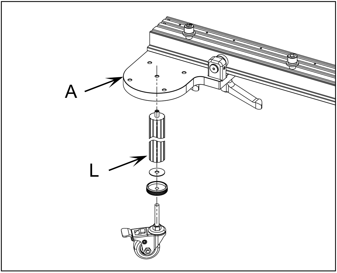
The eccentric wheel assembly (a1) provides auxiliary support and guidance for the Shark column. If the wheel needs repositioning, loosen the set screw (a2) to adjust the eccentric wheel assembly position, then re-tighten once aligned.
The Shark S-10 includes an optional support leg assembly that can be installed to promote smoother sliding movement, prevent wear on the rear rail, and reduce strain on the column bearings. Installation is recommended, particularly when the guard will be frequently repositioned.
Because of height differences between saw models and the added height of a mobile base (if used), you may find that the provided leg is too short without the extension or too long with the extension installed.
If this occurs, the extension can be shortened using a metal hacksaw or similar appropriate cutting tool. After cutting, the M8×1.25mm threads on the cut end will need to be re-tapped to allow the caster stem to thread in properly.
If no modifications to the leg are needed, follow these steps to install the support leg (L) under the column mounting bracket (A):
Unthread the setscrew from the leg extension and set the caster stem to its shortest length. This gives you the most adjustment range once the leg is mounted.
Position the leg under the column mounting bracket (A) as shown in Fig. 5. Thread the setscrew through the mount and into the leg underneath, then rotate the setscrew and leg in opposite directions simultaneously until both are fully tightened and the leg is secured firmly in place.
Adjust the leg length and caster stem so the caster makes even contact with the floor. Once set, confirm there is no binding in the caster rollers — the caster should roll freely without resistance or tilting. If binding occurs, adjust the leg height or caster stem slightly and recheck.
For installation assistance or questions about compatibility with your specific rear rail, please contact our support team or call 888-211-0397.
Was this article helpful?
That’s Great!
Thank you for your feedback
Sorry! We couldn't be helpful
Thank you for your feedback
Feedback sent
We appreciate your effort and will try to fix the article