Big Eye B-36/B-52 Rip Fence System: Sawstop ICS/PCS Installation
Created by Gabriel Izzo, Modified on Thu, 21 May at 11:40 AM by Gabriel Izzo
The Harvey Big Eye Rip Fence System can be mounted to SawStop ICS and PCS table saws with some modifications required. This guide provides step-by-step instructions to ensure a smooth, precise installation.
SawStop left extension wings are wider than those of the Harvey Alpha Series. This affects how the rails need to be positioned:
| Model | Left Extension Wing Width |
|---|---|
| SawStop PCS | 12″ |
| SawStop ICS | 10″ |
| Harvey Alpha Series | 7-9/32″ |
To compensate for the wider wings, the rails can be shifted to maintain the desired 36" or 52" rip capacity to the right of the blade, depending on the model.
Because the Big Eye fence body is T-shaped and wider in the front than the rear, position the rear rail so the rear clamping mechanism remains securely engaged when the fence is moved to the left bumper on the front guide rail.
If the rails are shifted to maximize use of the left table surface (e.g. with a wider left wing), note that rip capacity to the right of the blade will be reduced.
Verify that 10 mm diameter through-holes are drilled in perfect vertical and horizontal alignment across the saw, from left to right. This ensures compatibility with the eccentric bolts used for Big Eye rail mounting in the T-track system.
If the original holes in the cast iron wings and extension table are at different heights, perform a quick test fit:
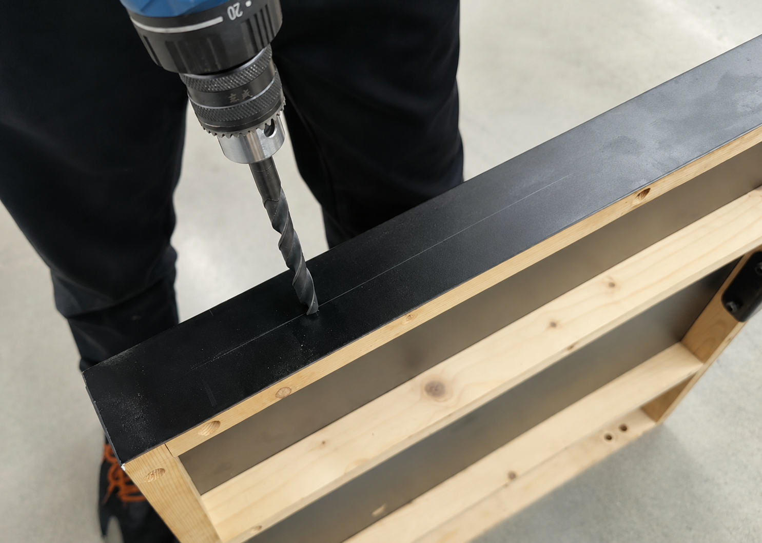
If the cast iron wing holes are positioned 29 mm from the tabletop to the hole center, drill 10 mm through-holes at the same height (29 mm) along the front and rear guide rail mounting surfaces, as shown in Figures 1–4. For a 52" extension table, three holes are recommended.
Inside the table, install flat washers, spring washers, and nuts, tightening them securely. Maintain a distance of 11.5 mm from the guide rail's top surface to the tabletop, as shown in Fig. 9.


Repeat the same procedure for the rear rail. Refer to the user manual for detailed diagrams and explanations regarding direct installation or modification-based installation depending on your specific SawStop model.


Legs for the ICS/PCS can be mounted after making modifications to accommodate the leg support brackets. Several options are available:
For help with your specific SawStop model or installation questions, please contact our support team.
Was this article helpful?
That’s Great!
Thank you for your feedback
Sorry! We couldn't be helpful
Thank you for your feedback
Feedback sent
We appreciate your effort and will try to fix the article