Turbo Wood Lathes FAQ: Troubleshooting Vibration or Noise After Spindle & Bearing Installation

Created by Gabriel Izzo, Modified on Thu, 18 Jun at 4:32 PM by Gabriel Izzo

Harvey Industries · Turbo Wood Lathes · FAQ & Troubleshooting
Troubleshooting Vibration or Noise After Spindle & Bearing Installation

If the spindle was disassembled and reinstalled and afterwards there is increased noise or vibration, there are a few possible causes to investigate. This guide walks through the most common causes and the measurement checks used to diagnose them.

Possible Causes
Cause 1 — Pulley Misalignment

The motor and spindle pulleys may not be perfectly aligned vertically after reassembly. Even slight vertical misalignment can create additional vibration and belt noise during operation.

Cause 2 — Bearing Side Shield Damage

The bearing side shields may have been slightly dented or damaged during removal and reinstallation. If the brass seals are rubbing against the bearing components, this can produce friction noise and additional vibration.

Cause 3 — Handwheel Runout (Most Common)

The most common cause of vibration after reassembly is handwheel runout. If the handwheel was reinstalled unevenly or tightened without monitoring runout with a dial indicator, it can become slightly skewed and create a rotating imbalance. If the vibration is more pronounced at certain speeds, this is characteristic of harmonic vibration caused by a rotating imbalance.

Note — T-60S Bearing Characteristics

The spindle bearings used in the T-60S are quite large, with ball elements nearly the size of marbles. Because of this, some intermittent noise that sounds like marbles rolling over each other can be normal and may be unavoidable even when everything is assembled correctly. A failed bearing on the T-60S will typically produce a very loud, consistent knocking noise — if the noise is intermittent rather than constant, a major bearing failure is unlikely.

⚠ Safety — Before Performing Any Checks
Unplug the lathe from power before beginning any checks or adjustments.
!
Perform all measurements by rotating the handwheel manually by hand only. Do not power on the machine during these checks.
Runout Measurement Checks
Use a magnetic-base dial indicator — complete all four checks
Factory Reference Tolerances

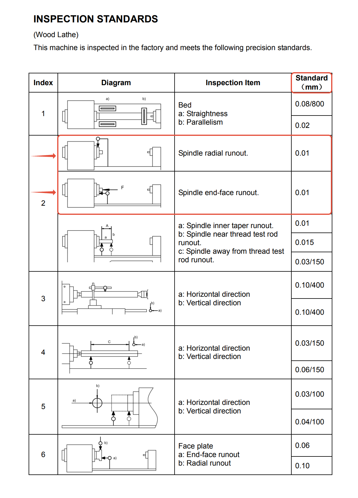
The following are the spindle inspection standards used during factory testing. Use these as your pass/fail reference for the measurements recorded in Checks 1 and 2.

Inspection ItemMaximum Tolerance
Spindle radial runout0.01 mm (0.0004")
Spindle end-face runout0.01 mm (0.0004")
Factory Inspection Standards — Reference Chart
Factory spindle inspection standards reference chart
1
Spindle Radial Runout

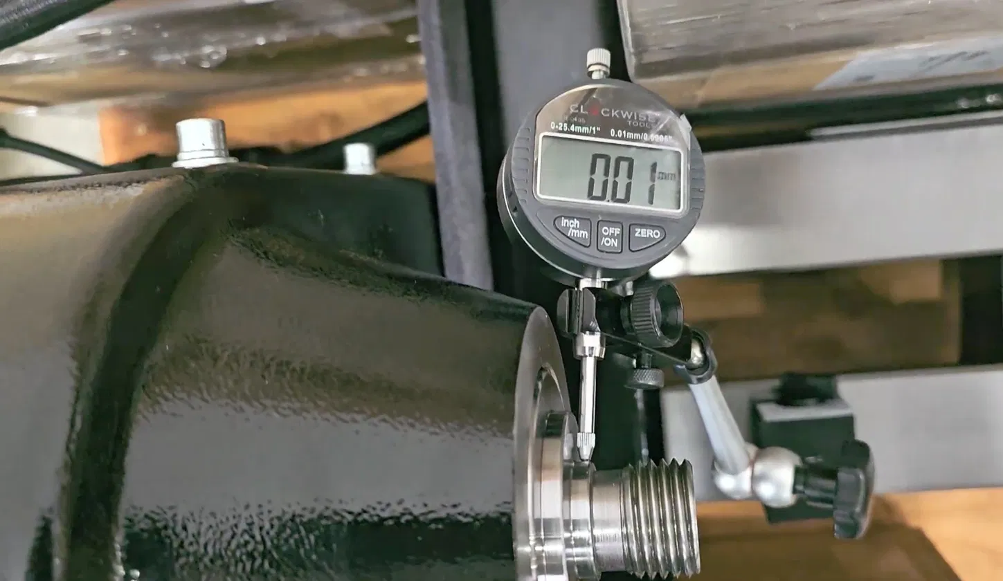
Mount the magnetic dial indicator securely to the lathe bed and position the indicator tip against the spindle's outside diameter.
1
Zero the indicator.
2
Slowly rotate the spindle by turning the handwheel by hand through a full revolution.
3
Record the total indicator reading (TIR).
Factory Standard: Spindle radial runout ≤ 0.01 mm (0.0004")
Spindle Radial Runout — Reference Photo
Dial indicator against spindle outside diameter
2
Spindle End-Face Runout

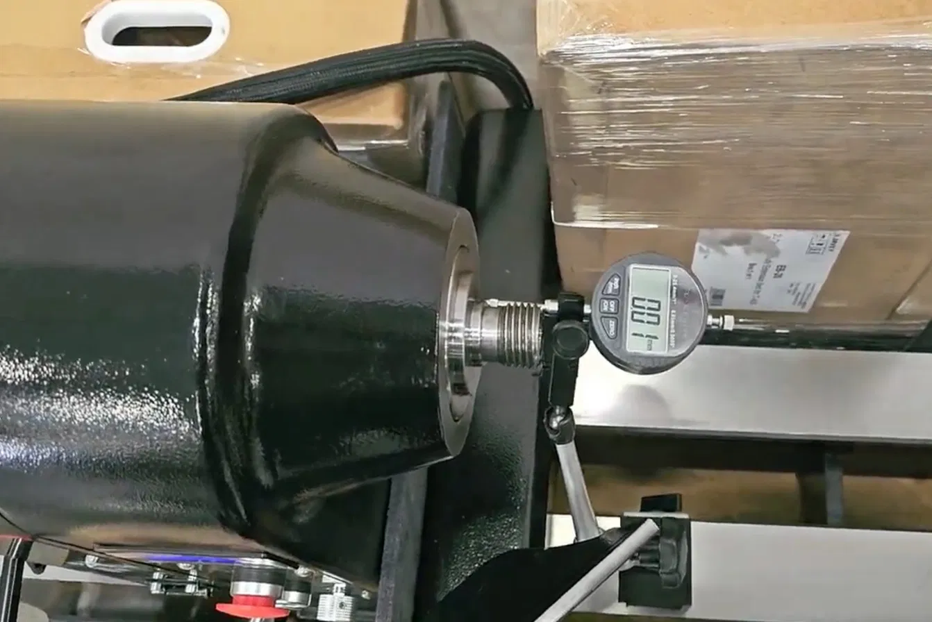
Move the indicator so the tip contacts the spindle shoulder face.
1
Zero the indicator.
2
Slowly rotate the spindle using the handwheel through a full revolution.
3
Record the total indicator reading (TIR).
Factory Standard: Spindle end-face runout ≤ 0.01 mm (0.0004")
Spindle End-Face Runout — Reference Photo
Dial indicator against spindle shoulder face
3
Handwheel Runout

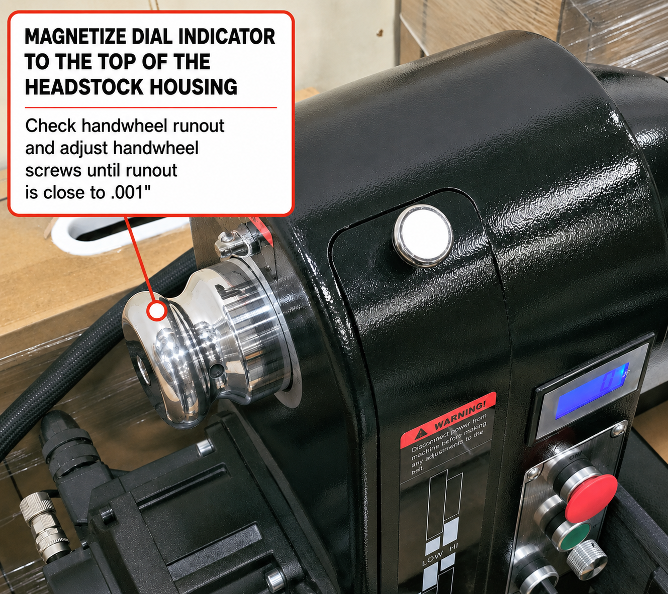
Mount the dial indicator to the top of the headstock and position the indicator tip against the handwheel face.

1
Zero the indicator.
2
Slowly rotate the handwheel through a complete revolution by hand.
3
Record the total indicator reading (TIR). If excessive runout is observed, proceed to the adjustment technique below.
Target: Handwheel runout ≤ 0.001" (0.025 mm)
Handwheel Adjustment Technique

If the handwheel screws are not tightened carefully, they can introduce runout and cause additional vibration and bearing stress. Use the following technique:
Lightly tighten both handwheel screws until they just make contact with the shaft — do not fully tighten yet.
Tighten the screws evenly, alternating back and forth between both screws in small increments.
Monitor the dial indicator throughout tightening — watch for runout increasing as you tighten. Aim to get both screws fully tight while keeping runout at or below 0.001".
If runout increases during tightening, back off slightly and retry, adjusting the relative tightness of each screw to balance the wheel.
Handwheel Runout — Dial Indicator Setup
Dial indicator mounted to headstock measuring handwheel runout
After Completing the Checks
If the issue persists, send us the following
1
A photo or video of the indicator setup for each test.
2
Your measured runout values for: spindle radial runout, spindle end-face runout, and handwheel runout.
3
Optionally, a short video showing the indicator while you slowly rotate the spindle or handwheel by hand.
Once we review the results we will be able to determine whether the spindle assembly or handwheel requires further adjustment, or whether the issue could be coming from other factors such as how the spindle was reseated into the housing or the condition of the bearings.
i

For further assistance diagnosing spindle vibration or noise, please contact our support team or call 888-211-0397.

Was this article helpful?

That’s Great!

Thank you for your feedback

Sorry! We couldn't be helpful

Thank you for your feedback

Let us know how can we improve this article!

Select at least one of the reasons
CAPTCHA verification is required.

Feedback sent

We appreciate your effort and will try to fix the article