Alpha HW110S Table Saw: Spindle and Bearing Replacement

Created by Gabriel Izzo, Modified on Tue, 26 May at 6:29 PM by Gabriel Izzo

Alpha HW110S Table Saw · Maintenance & Repair
Spindle & Bearing Replacement
Applicable Models
Alpha HW110S Series Table Saws (4HP)
Overview

This guide covers the spindle and bearing replacement procedure for the Alpha HW110S table saw. Steps and diagrams are referenced from the HW110S Instruction Manual. Ensure the saw is fully disconnected from power before beginning any disassembly.

Table Saw Safety
+
Disconnect the table saw from power before performing any maintenance or repairs. Never work on internal components with the machine connected to a power source.
+
Wear safety glasses and cut-resistant gloves throughout this procedure. Bearing components and spindle parts can have sharp edges.
+
Wear fitted clothing and avoid dangling jewelry or loose accessories when working around the saw.
+
Read the instruction manual before beginning. Familiarize yourself with the safety features and operational guidelines for your specific model.
Is Replacement Necessary? — Checking Arbor Runout

Before replacing the spindle and bearings, verify that the arbor is actually the source of the problem. A dial indicator is required for this test — it is the definitive tool for diagnosing runout and wobble on rotating parts such as blades, arbors, spindles, and shafts. It lets you confirm whether runout exists, measure how much, and pinpoint likely causes such as loose fasteners, bent shafts, or failing bearings.
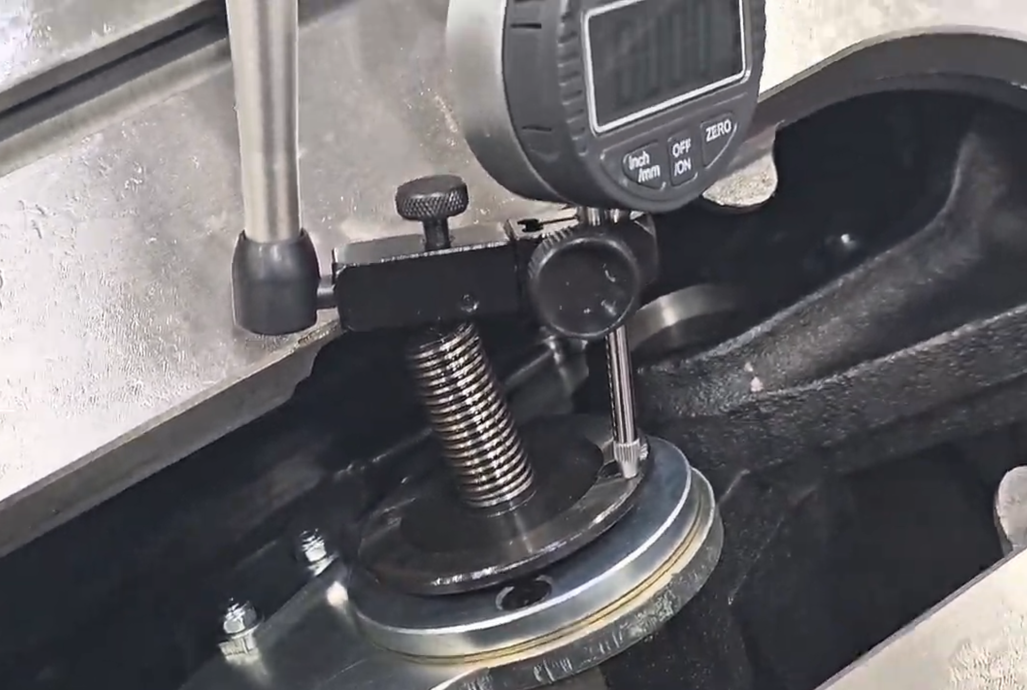
Place the dial indicator tip against the edge of the arbor flange, avoiding the locating pin holes (see photo below) and zero out the indicator.
Rotate the arbor from the belt side to avoid interfering with the indicator reading and read the total indicated runout. The acceptable axial runout limit is 0.02 mm (0.00078″).
If runout exceeds 0.02 mm, spindle and bearing replacement is likely required. If runout is within spec, investigate other causes before disassembly.
 Max Axial Runout 0.02 mm  /  0.00078″ 
Dial Indicator Placement — Arbor Flange (Avoid Locating Pin Holes)
Dial indicator placement on arbor flange avoiding locating pin holes
Video — How to Check Arbor Runout with a Dial Indicator
Replacement Procedure
1
Remove the Blade, Throat Plate, and Arbor Components
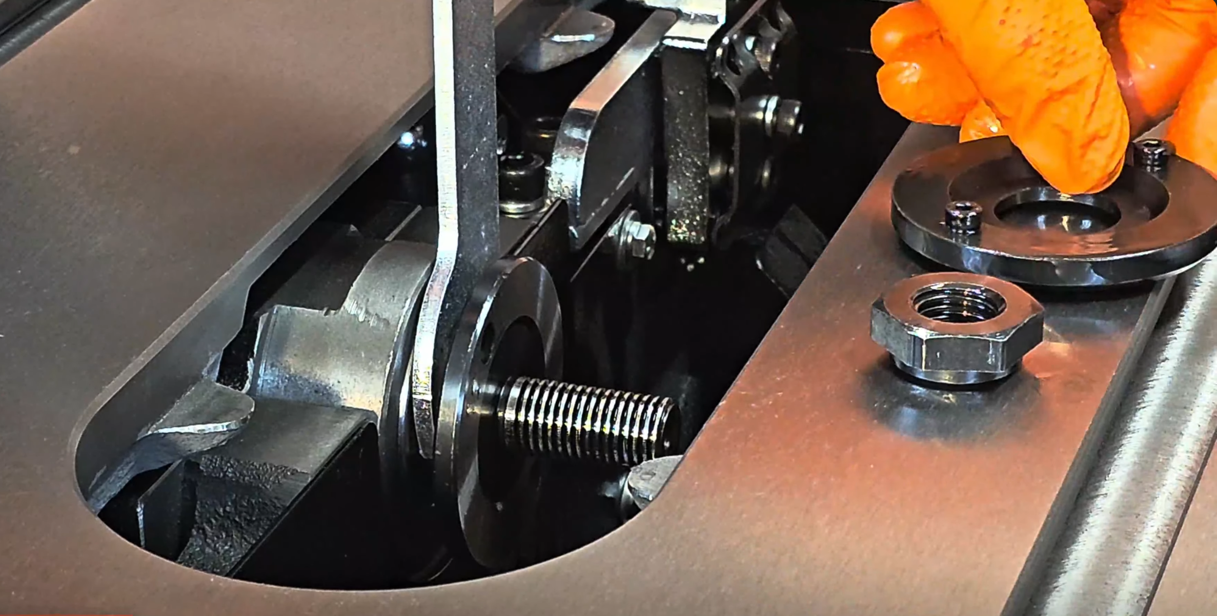
Remove the throat plate insert from the table.
Using a 24mm wrench on the arbor shaft and a 27mm wrench on the arbor nut, loosen and remove the arbor nut and flange washer.
Carefully slide the saw blade off the arbor shaft and set it aside safely.
Step 1 — Remove Blade & Arbor Components
Step 1 - remove blade and arbor components
2
Detension the Belt & Remove the Pulley
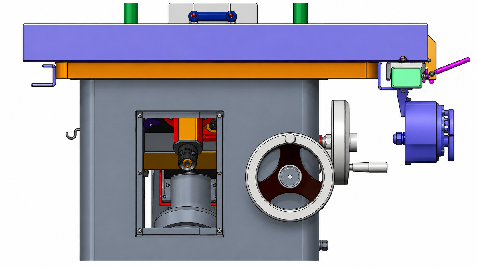
Open the saw cabinet and detension the drive belt, then disconnect it from the arbor pulley.
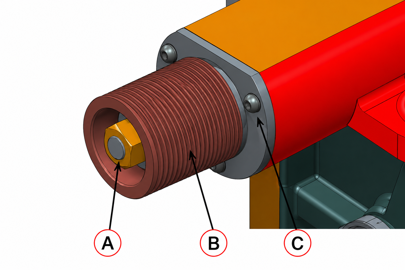
Remove the arbor lock nut (A) and the arbor lock washer.
Remove the set screws securing the pulley to the shaft.
Carefully slide the pulley (B) off the shaft — do not drop or lose the pulley key that sits in the shaft/pulley keyway.
Step 2a — Belt, Lock Nut & Washer Removal
Step 2a - belt detension, lock nut and washer removal
Step 2b — Pulley & Key Removal
Step 2b - pulley and key removal
3
Remove the Collar, Spindle, and Bearings
Remove the three screws securing the collar (C) and remove the collar from the housing.
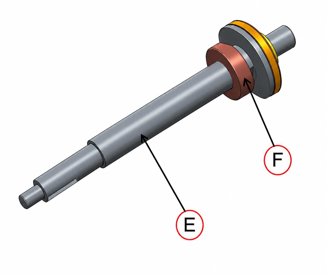
Using a large punch and hammer, carefully tap the spindle shaft (E) out of the arbor housing — work from the pulley side toward the blade side. Bearing (F) and the wave lock washer will come out with the shaft.
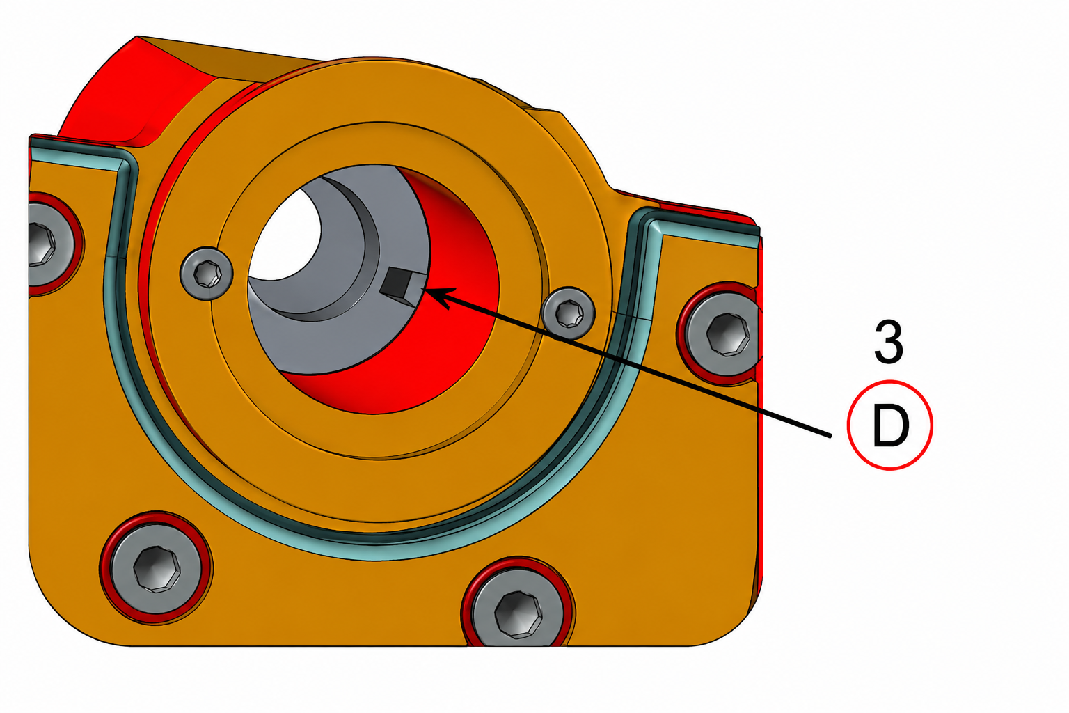
With the collar removed, press out bearing (D) and its bearing set collar from the housing — work from the blade side outward toward the pulley side.
Note the order and orientation of each component before removal — correct reinstallation depends on this.
Step 3a — Remove Collar & Tap Out Spindle (E) and Bearing (F)
Step 3a - remove collar, tap out spindle and bearing F
Step 3b — Press Out Bearing (D) & Set Collar
Step 3b - press out bearing D and set collar
Install New Bearings & Reassemble
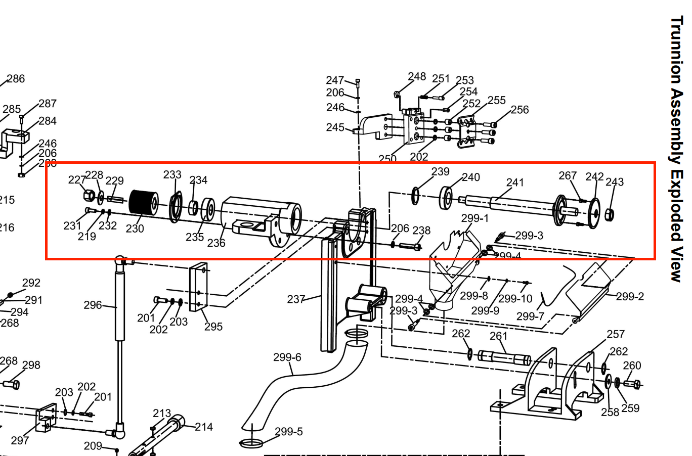
Perform the reverse of the removal steps above, following the parts diagram for correct bearing order and orientation.
Press the new bearings into the housing in the correct order shown in the parts diagram.
Reinsert the spindle shaft and reassemble the arbor assembly into the trunnion.
Confirm the arbor nut and pulley are fully secured to the arbor shaft.
Reconnect the drive belt and tension it per the belt tensioning procedure.
If you have a dial indicator, check the arbor flange runout now to confirm it is within the 0.02 mm tolerance before reinstalling the blade.
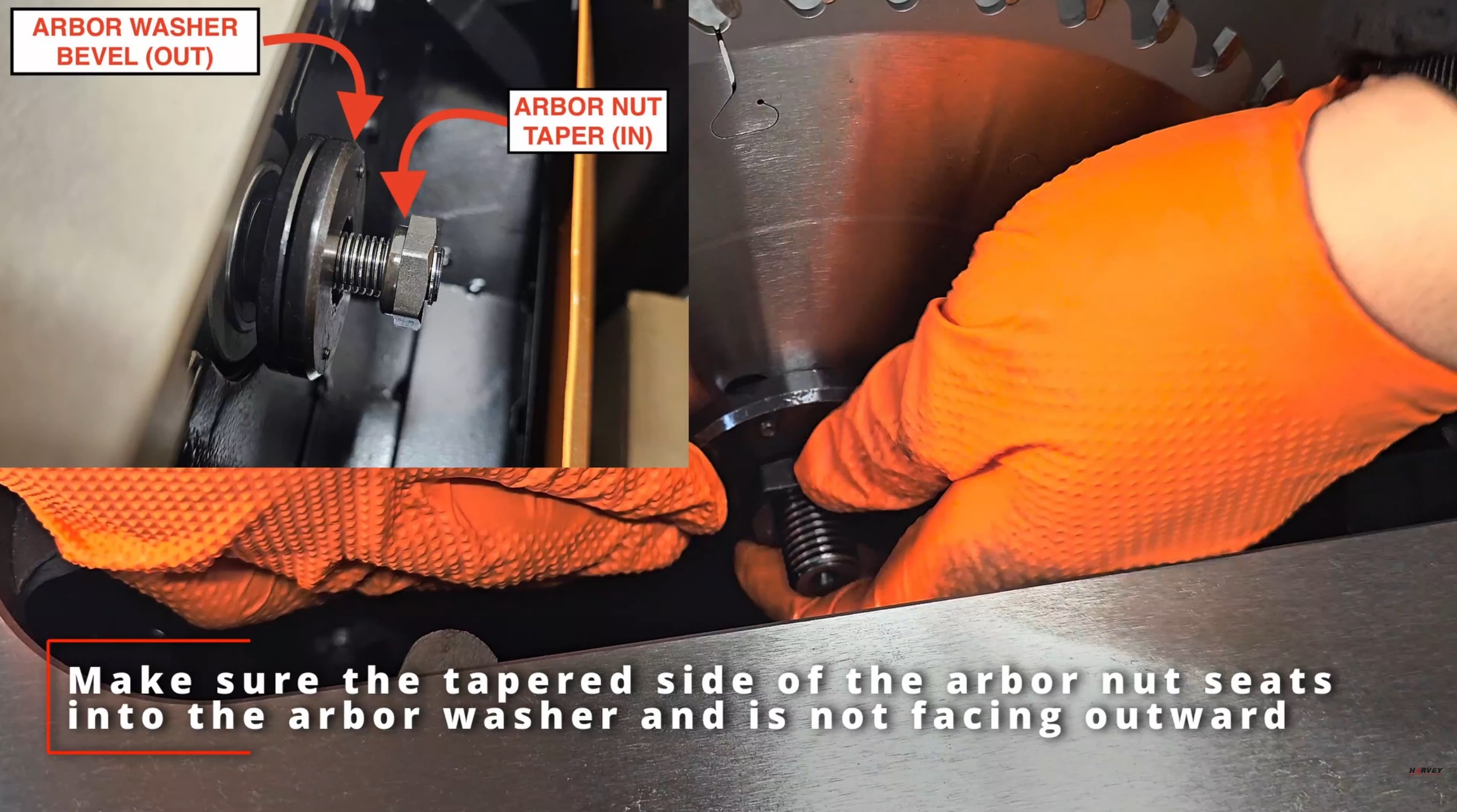
Once confirmed, reinstall the blade, flange washer, and arbor nut on the blade side.
The arbor installation is now complete! Reconnect power and test for smooth operation without excessive blade runout, vibration, or wobble.
Step 4a — Parts Diagram & Bearing Order Reference
Parts diagram showing correct bearing order and orientation
Step 4b — Arbor Washer and Nut Installation Orientation
Arbor washer and nut installation orientation
i

For assistance with spindle or bearing replacement, or to order replacement parts, please contact our support team.

Was this article helpful?

That’s Great!

Thank you for your feedback

Sorry! We couldn't be helpful

Thank you for your feedback

Let us know how can we improve this article!

Select at least one of the reasons
CAPTCHA verification is required.

Feedback sent

We appreciate your effort and will try to fix the article