Spider Series M-1500PRO: Troubleshooting Feet Not Locking or Cams Out of Sync When the Pedal is Pressed

Created by Gabriel Izzo, Modified on Mon, 18 May at 2:37 PM by Gabriel Izzo

Spider Series M-1500Pro · Troubleshooting
Feet Not Locking or Cams Out of Sync When Pedal is Pressed

This guide provides step-by-step instructions for correctly assembling and adjusting the pedal assembly on the Spider M-1500Pro mobile base to ensure all cams are aligned and functioning in sync. These adjustments must be made carefully to ensure proper operation.

Safety Warnings & Precautions
+
Heavy equipment: Ensure the machine and base are stable and properly supported before performing any adjustments.
+
Stabilization: Immobilize the mobile base before making any adjustments. Use wheel chocks if available to prevent accidental movement.
+
PPE: Wear gloves and safety footwear when handling heavy components or tools.
i
Always refer to the official manual for your specific model — it takes precedence over this guide in any case of discrepancy.
Tools Required
3mm Hex Key set screws
4mm Hex Key cap screws
Step-by-Step: Assembling & Adjusting the Pedal Assembly
1
Verify the Initial Position of the Cams

Before starting the pedal assembly, ensure that all cams are fully raised (in the highest position) at the same time. This is crucial — if the cams are out of sync the pedal assembly may fail to function properly. Set all four regulating screws on the corner casters to be centered in the middle of the channel. Screws set too high or too low will affect functionality when pressing the pedal to extend and lock the feet.
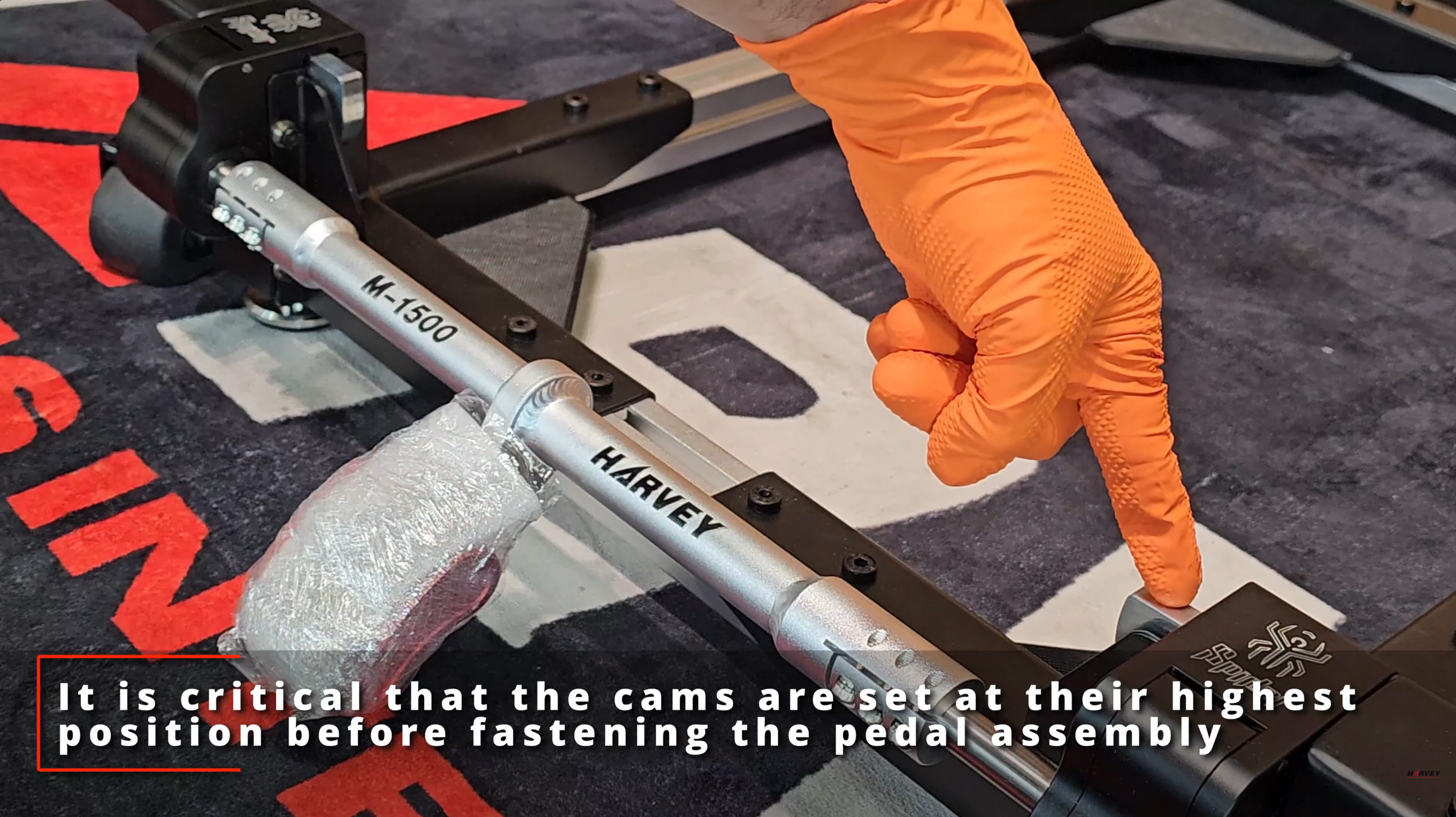
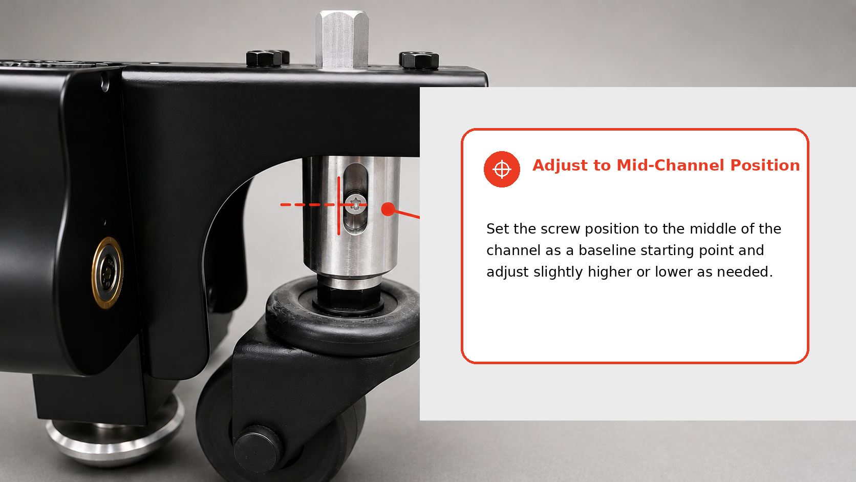
Tip: If unsure whether the cams are aligned, gently rotate them by hand to confirm all are at the highest position while the pedal assembly is still loose on the camshafts.
Step 1 — Cams at Highest PositionFig. 1
Step 1 — All cams raised to highest position
Step 1 — Regulating Screws Centered in ChannelFig. 2
2
Position the Pedal Assembly

With the cams fully raised, position the pedal assembly over the camshafts at approximately a 30-degree angle with the ground. Keep the pedal loose on the camshafts at this stage — do not fasten the pedal assembly until the cams are correctly aligned and the pedal is at the correct angle.
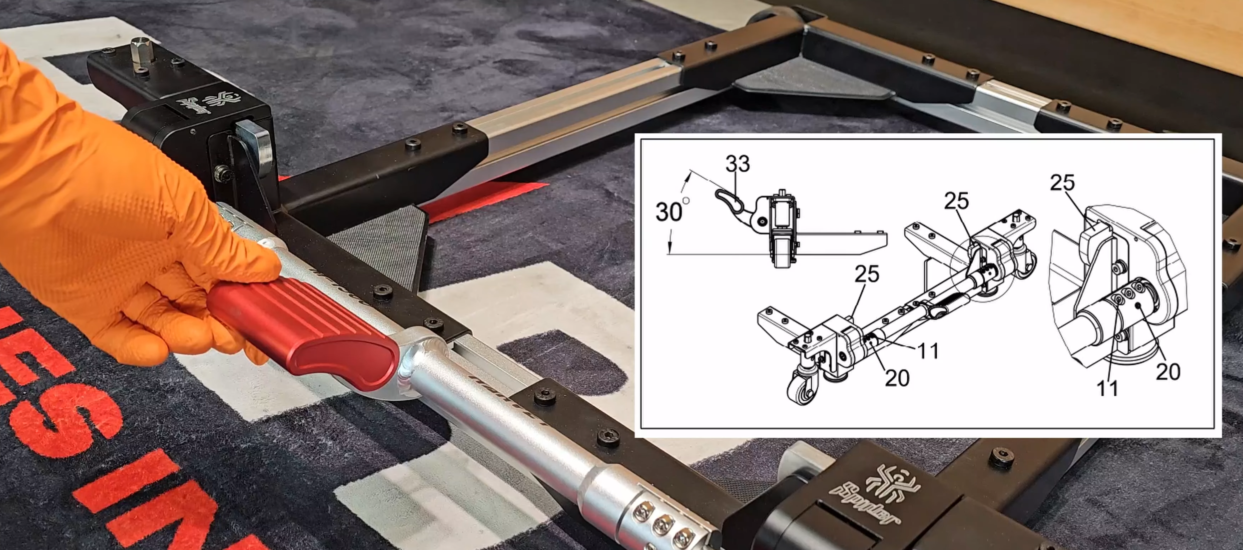
Step 2 — Position the Pedal AssemblyFig. 3
Step 2 — Position the Pedal Assembly
3
Tighten the Two Set Screws

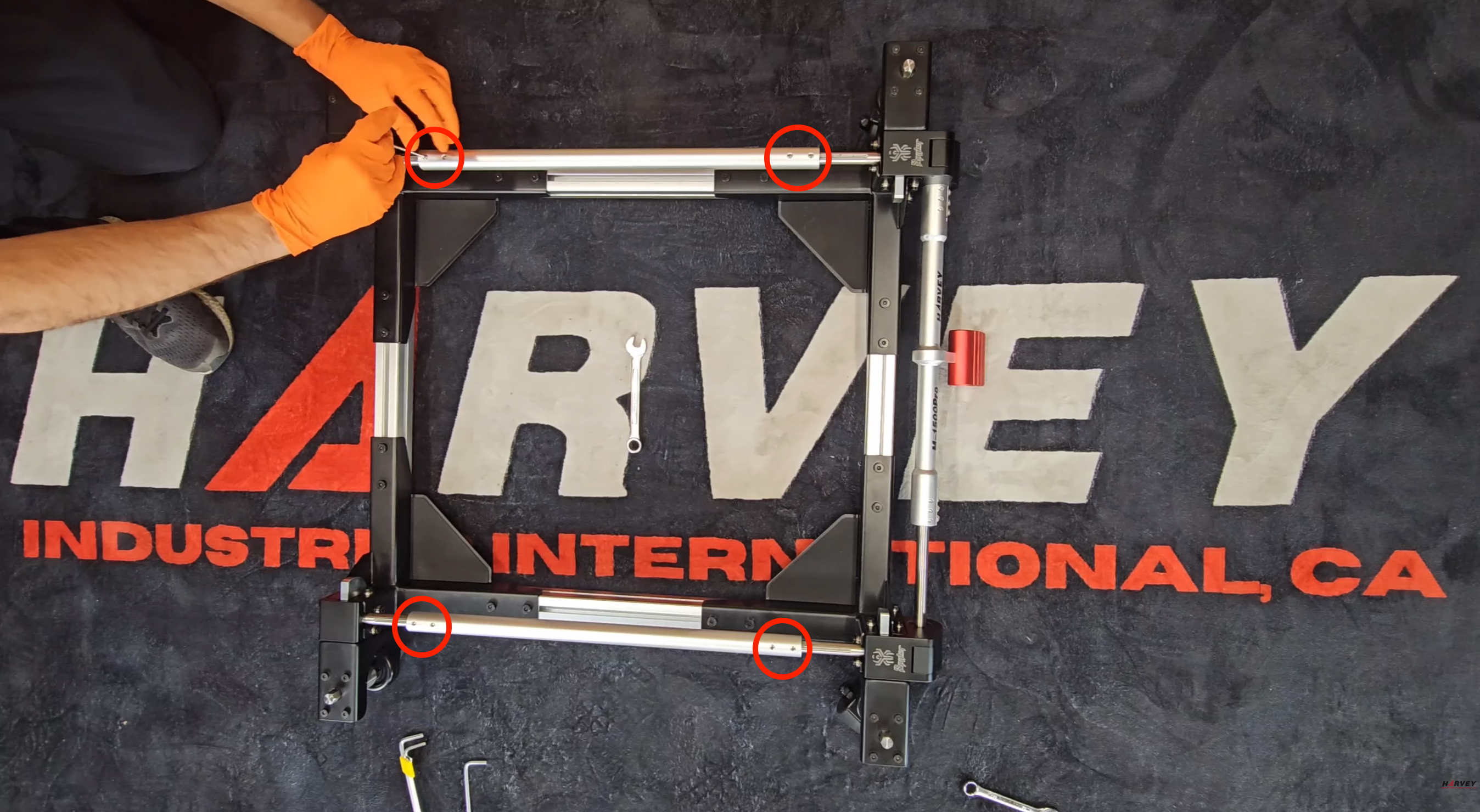
Once the pedal assembly is positioned at approximately a 30-degree angle with the ground and all four cams are fully in the UP position, begin by tightening the two set screws on the pedal assembly as securely as possible to prevent any slipping.
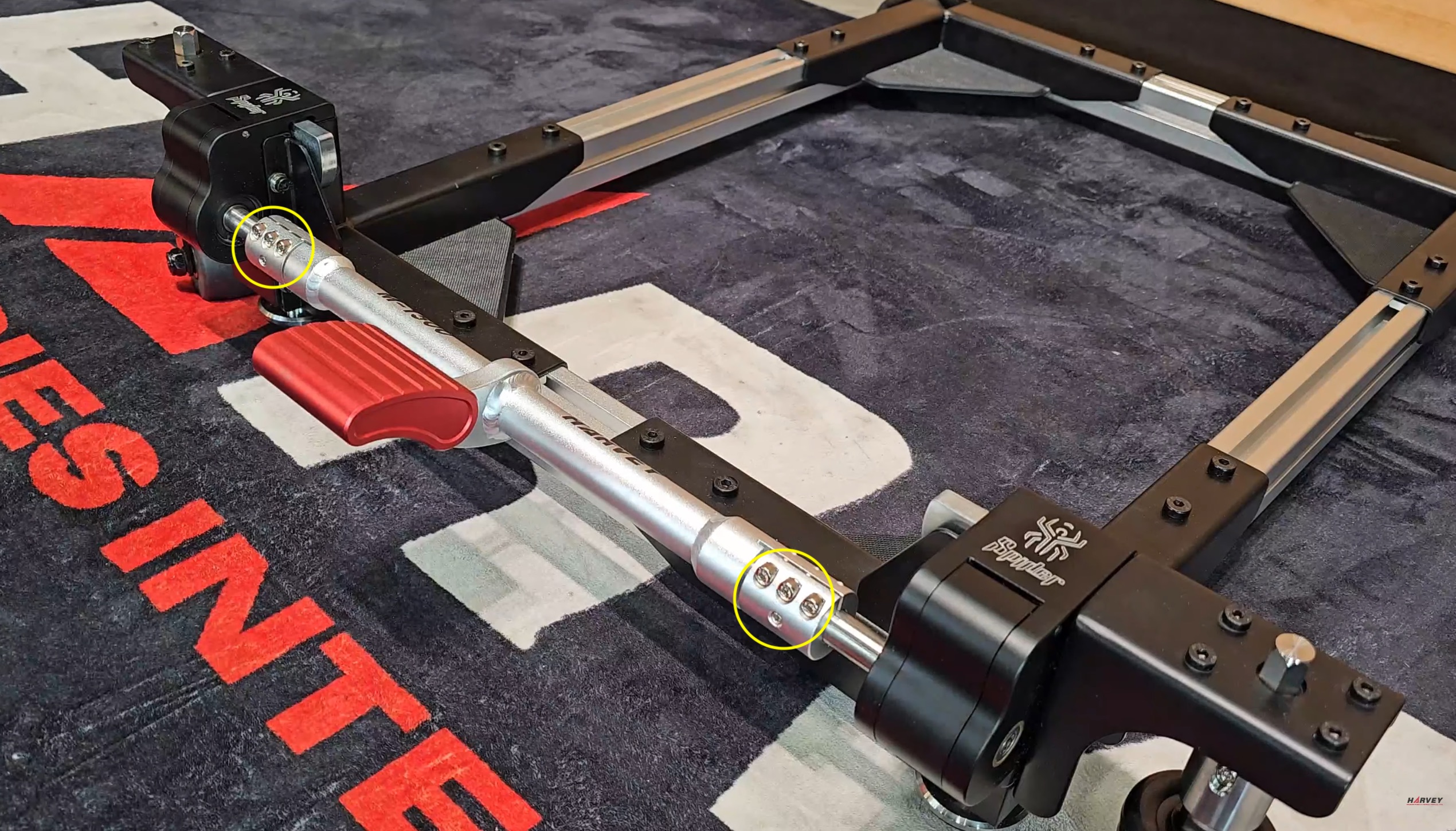
Important: Ensure the pedal assembly is aligned properly with both sides of the camshafts. If either side slips it will lead to improper synchronization of the pedal and cams.
Step 3 — Set Screw & Cap Screw LocationsFig. 4
Step 3 — Pedal assembly screw locations
4
Tighten the Six Cap Screws

After the set screws are tightened, tighten the six cap screws to fully secure the pedal assembly in place.

Tip: Tighten screws alternately across the pedal assembly to ensure even pressure distribution and prevent the assembly from becoming misaligned.
5
Double-Check the Tightness of All Fasteners

As you tighten the screws, check that none of the pedal fasteners become loose or shift out of place. Tightening one side may cause the opposite side to loosen.

Tip: Go back and forth between tightening screws to ensure all are fully tightened. Verify no screws can be tightened further once all cams are in the UP position.
6
Check for Cam Synchronization

After the pedal assembly is securely fastened, test the cams by gently operating the pedal. All cams should move in sync without any side slipping.

Important: If any cam has moved lower or is out of sync, raise it fully to its highest position before continuing. Failure to do so will result in cam misalignment and prevent the pedal from locking properly.
Final Inspection

Once all screws are tight and the cams are properly aligned, conduct a final inspection. Confirm:
The pedal operates smoothly without any resistance or misalignment.
All screws and fasteners are securely tightened.
The mobile base is stable with no parts slipping or shifting when the pedal is engaged.
Additional check: If everything above looks normal but the issue persists, verify that the screw shown in the image below is properly seated in the groove of the guide rod. A screw not fully seated will prevent the feet from locking even if the cams are aligned.
Step 7 — Guide Rod Screw Seating CheckFig. 5
Step 7 — Screw seated in guide rod groove, highlighted with red circle
Video Walkthrough

The video below demonstrates the cam synchronization and pedal assembly adjustment process.

M-1500Pro Unboxing & Assembly Video
Pedal assembly  ·  cam alignment  ·  guide rod check
 

Disclaimer: This guide provides general guidance on the assembly and adjustment of the pedal assembly on the M-1500Pro. Always refer to the official instruction manual for your specific equipment model — it takes precedence over this guide in any case of discrepancy.

i

If the issue persists after following these steps, please contact our support team for further assistance.

Was this article helpful?

That’s Great!

Thank you for your feedback

Sorry! We couldn't be helpful

Thank you for your feedback

Let us know how can we improve this article!

Select at least one of the reasons
CAPTCHA verification is required.

Feedback sent

We appreciate your effort and will try to fix the article