Gyro Air G-700: Troubleshooting Err09 Under-voltage - GFCI Tripping

Created by Gabriel Izzo, Modified on Tue, 19 May at 3:14 PM by Gabriel Izzo

Gyro Air G-700 · Troubleshooting
Error Code Err09 — Under-Voltage & GFCI Tripping
Applicable Model
Gyro Air G-700 Dust Processor

If your G-700 is tripping a GFCI breaker or displaying an Err09 Under/Over Voltage error, this can often be resolved by removing the EMC filter screw on the side of the VFD. Follow the steps below to safely access and adjust the necessary component.

What is the EMC Filter?

The VFD has a built-in EMC (Electromagnetic Compatibility) filter — a safety capacitor that prevents the drive from generating or being affected by electromagnetic disturbance. With the EMC screw installed, the unit can be more sensitive to current leakage and may trip GFCI outlets or display Err09. Removing the screw reduces leakage current to ground and typically resolves the issue.

Electrical Safety — Read Before Proceeding
+
Ensure the machine is OFF and unplugged. Disconnect the machine from power and allow a minimum of 10 minutes for internal capacitors in the VFD to fully discharge before servicing. Always verify voltage has dissipated using a properly rated multimeter before touching any internal electrical components.
+
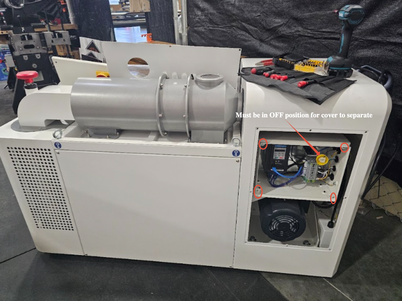
The power switch must be in the OFF position before removing the electrical box cover — it will be locked if the switch is ON.
+
Only handle the EMC screw — do not touch, modify, or disturb any other wiring or components inside the electrical box.
Verify Power Supply First

Before proceeding with the EMC screw removal, confirm that the G-700 is receiving the correct power supply:

Voltage 208V – 240V single-phase
Circuit Dedicated 20A / NEMA 6-20R
Breaker 240/250V double-pole
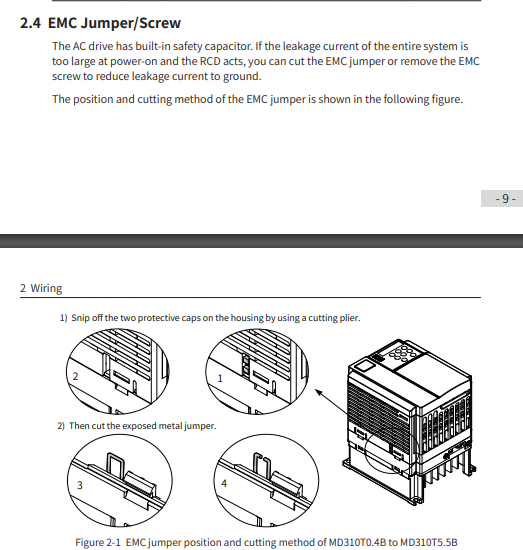
EMC Filter Screw Location — Reference Diagram
Inovance VFD — EMC Filter Screw Diagram Fig. 1
Inovance VFD EMC filter screw location diagram
Steps to Remove the EMC Filter Screw
1
Remove the Rear Panel

Remove the rear panel that covers the main power switch to expose the internal components.

2
Access the Electrical Box

Remove the four screws securing the electrical box cover. Ensure the main power switch is in the OFF position before removing the cover.

Step 2 — Electrical Box Cover Screws Fig. 2
Electrical box cover screw locations
3
Adjust the VFD Position

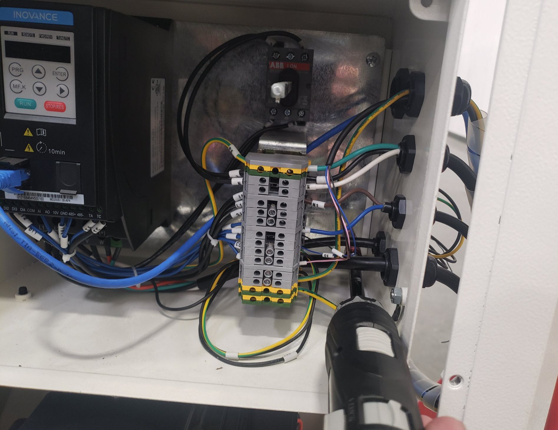
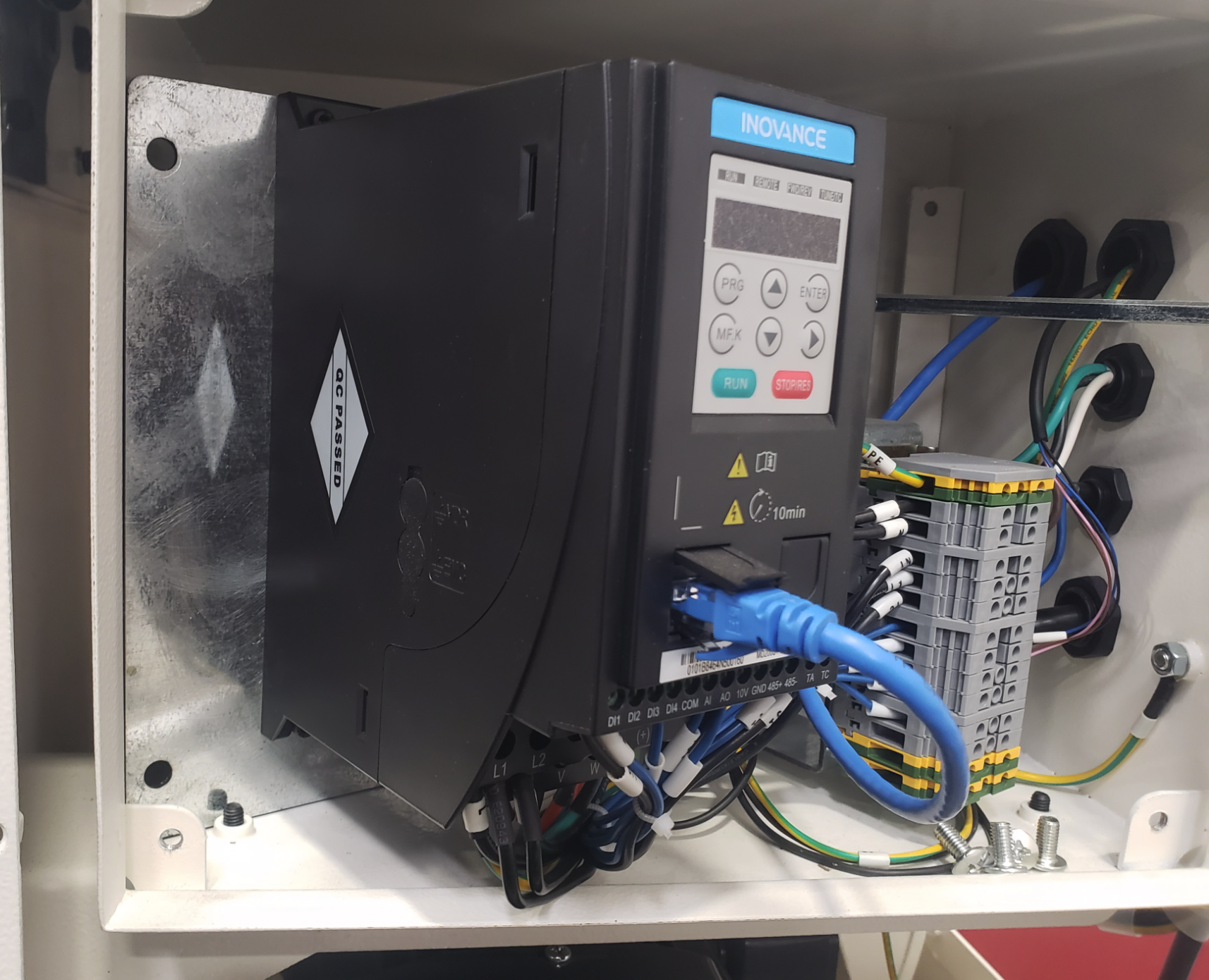
Remove the four screws holding the component plate against the back wall of the electrical box. Carefully adjust the position of the VFD on the left side to improve access to the EMC screw.

Step 3 — Component Plate Screws Fig. 3
Component plate screw locations
Step 3 — VFD Position Adjustment Fig. 4
VFD position adjustment
Step 3 — VFD Repositioned Fig. 5
VFD repositioned for EMC screw access
4
Remove the EMC Filter Screw

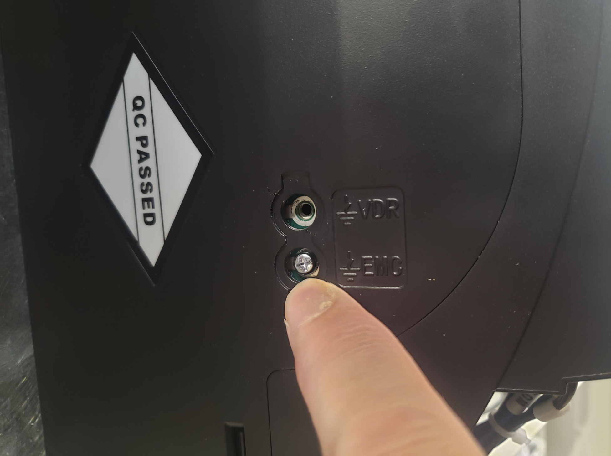
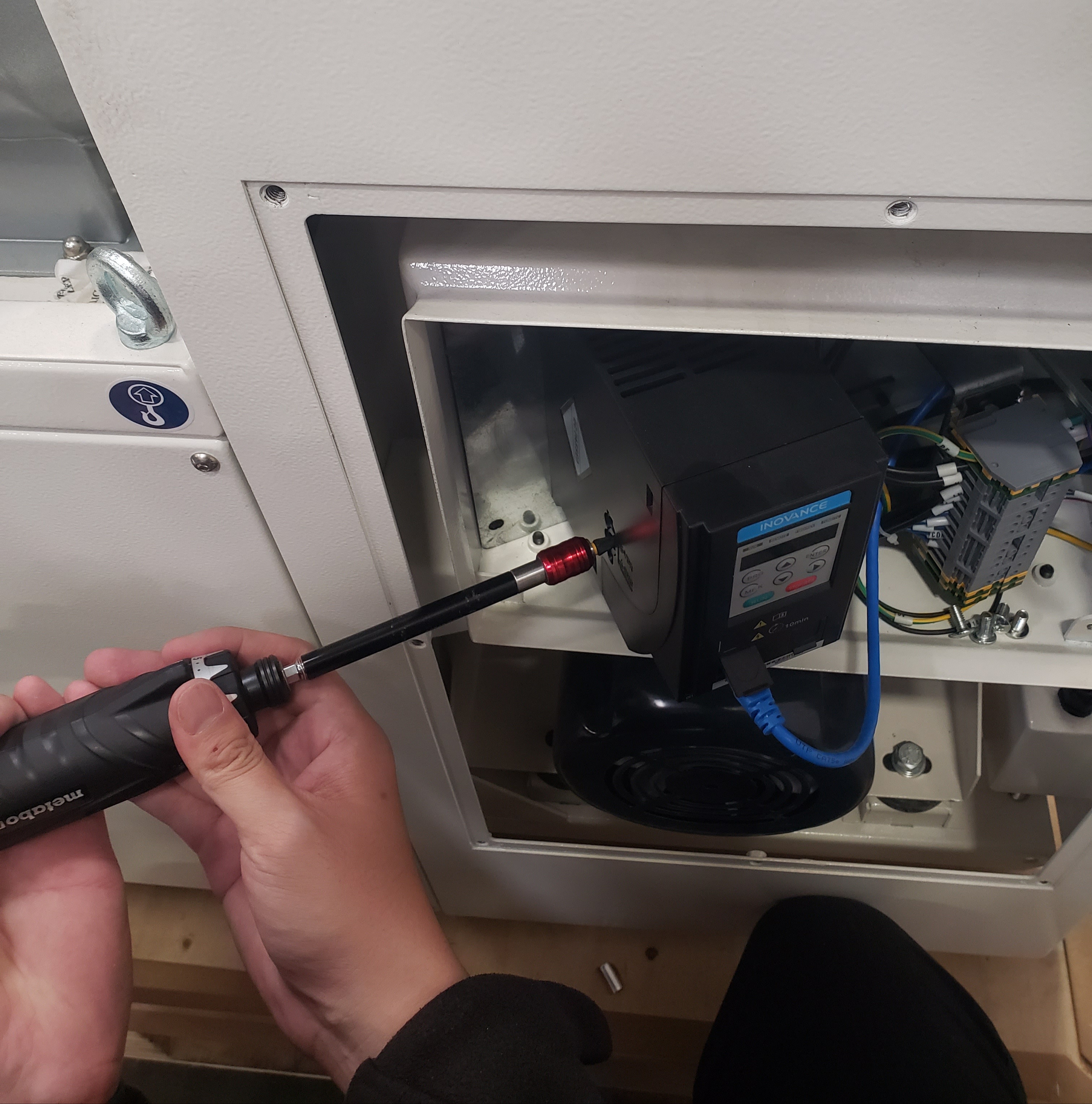
Locate and remove the screw labeled "EMC" on the side of the VFD. This may require a screw gun with a longer extension or a long screwdriver depending on placement within the unit. Keep the screw in a safe place.

Step 4 — EMC Screw Location Fig. 6
EMC screw location on VFD
Step 4 — EMC Screw Detail Fig. 7
EMC screw close-up detail
5
Reassemble the Electrical Box

Reattach the component plate to the rear wall of the electrical box. Replace the electrical box cover with the switch in the OFF position and secure it with the four screws.

Test the Machine

Plug in the machine and turn the switch to the ON/Standby position. Attempt to start using either the remote control or the Basic Operating Panel (BOP) and check if the Err09 error has cleared.

If the error persists after removing the EMC screw, the inverter may be faulty and require replacement. Contact our support team for further assistance.
i

If the issue persists after completing these steps, please contact our support team.

Was this article helpful?

That’s Great!

Thank you for your feedback

Sorry! We couldn't be helpful

Thank you for your feedback

Let us know how can we improve this article!

Select at least one of the reasons
CAPTCHA verification is required.

Feedback sent

We appreciate your effort and will try to fix the article