Alpha HW615/Ambassador C14 Band Saws: Adjusting the Table Support Frame Square to the Blade Front and Back

Created by Gabriel Izzo, Modified on Tue, 19 May at 11:20 AM by Gabriel Izzo

Band Saw · Table Adjustment
Adjusting the Table Support Frame Square to the Blade — Front & Back
Applicable Models
Alpha HW615
Ambassador C14

To adjust the squareness of the bandsaw table surface relative to the back edge (spine) of the blade, follow the instructions below to achieve a precise 90-degree alignment.

Proper squareness is especially important when making curved cuts on taller workpieces, as it ensures consistent blade contact from top to bottom. If the blade is not square to the table — meaning the spine is angled — it can lead to uneven tracking through the cut and potential blade twisting at either the top or bottom of the workpiece.
Safety Precautions — Read Before Proceeding
+
Disconnect power — always unplug the band saw from the power source before performing any maintenance or adjustments to prevent accidental startup.
+
Wait for all moving parts to stop — ensure the blade and all components have come to a complete stop before starting any work.
+
Wear PPE — use safety glasses and cut-resistant gloves when working around the blade or sharp edges.
+
Use proper tools only — use appropriate well-maintained tools. Do not use makeshift tools or overtighten fasteners.
i
These instructions are intended for individuals familiar with band saw operation and basic mechanical maintenance. If you are not comfortable performing any of these steps, consult a qualified technician or contact Harvey Customer Support before proceeding. Improper maintenance may result in personal injury, equipment damage, or voiding of the warranty.
Tools Required
5mm Hex Wrench Set Screws #427
Adjustable Wrench Hex Cap Bolts #414
Adjustment Steps
1
Tilt the Table and Loosen the Hex Cap Bolts

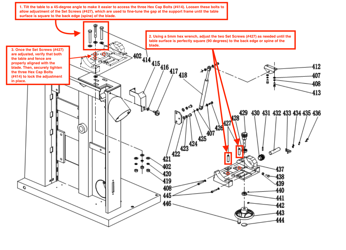
Tilt the table to a 45-degree angle to make it easier to access the three Hex Cap Bolts (#414). Loosen these bolts to allow adjustment of the Set Screws (#427), which are used to fine-tune the gap at the support frame until the table surface is square to the back edge (spine) of the blade.

Tilting to 45° first provides the clearance needed to comfortably reach both the cap bolts and set screws without the table being in the way.
2
Adjust the Two Set Screws

Using a 5mm Hex Wrench, adjust the two Set Screws (#427) as needed until the table surface is perfectly square — 90 degrees — to the back edge or spine of the blade.

↻ Clockwise Tightens screw & raises the table
↺ Counter-clockwise Loosens screw & lowers the table
Verify Alignment and Tighten the Cap Bolts

Once the Set Screws (#427) are adjusted, verify that both the table and fence are properly aligned with the blade. Then, securely tighten the three Hex Cap Bolts (#414) to lock the adjustment in place.

Important: Always re-check table squareness after tightening the cap bolts, as tightening can sometimes shift the adjustment slightly.
Reference Diagram
Table Support Frame — Set Screws #427 & Hex Cap Bolts #414
Diagram showing Set Screws #427 and Hex Cap Bolts #414 locations on the table support frame
i

Need further assistance with table alignment? Please contact our support team.

Was this article helpful?

That’s Great!

Thank you for your feedback

Sorry! We couldn't be helpful

Thank you for your feedback

Let us know how can we improve this article!

Select at least one of the reasons
CAPTCHA verification is required.

Feedback sent

We appreciate your effort and will try to fix the article