Gyro Air G-700: Troubleshooting Error Code Err15 (Inovance VFD)

Created by Gabriel Izzo, Modified on Tue, 19 May at 2:58 PM by Gabriel Izzo

Gyro Air G-700 · Troubleshooting
Error Code Err15 — Inovance VFD
Applicable Model
Gyro Air G-700 — Inovance VFD Models Only

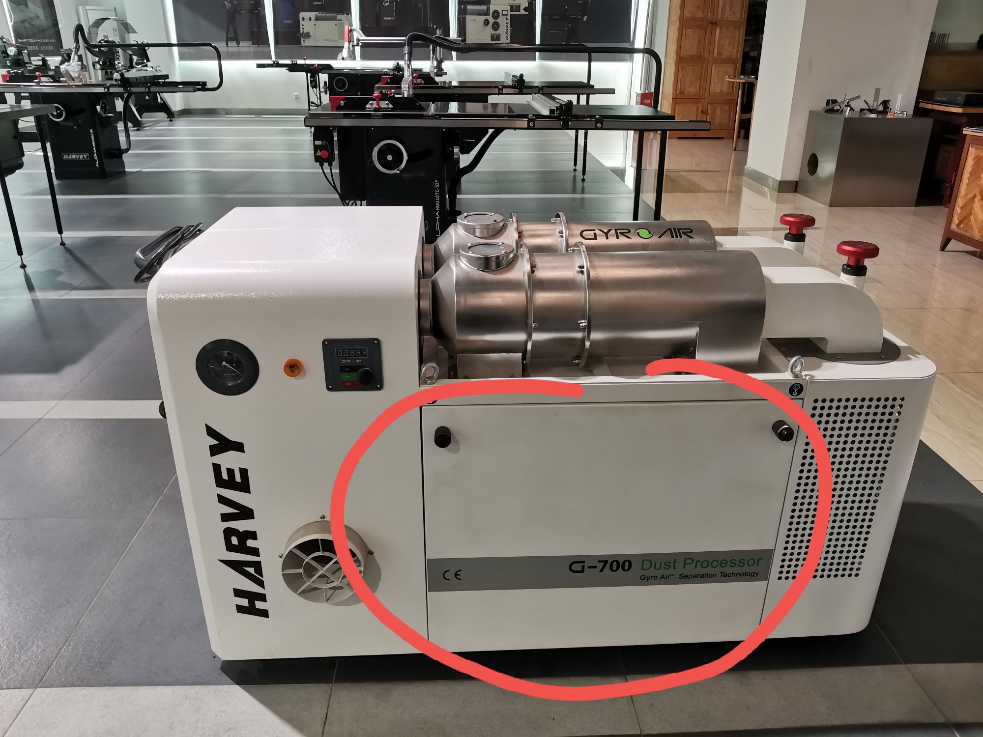
The G-700 uses a Variable Frequency Drive (VFD) as the central hub that all electrical components connect through to communicate with the motor. This includes the dust bin full sensor and the remote receiver. An Err15 code indicates an external fault has been triggered by one of these components.

Electrical Safety — Read Before Proceeding
+
Turn the machine OFF and unplug it from the power source before accessing the electrical box, removing panels, or checking any wiring connections.
+
The power switch must be in the OFF position to remove the electrical box panel — it will be locked in place if the switch is ON.
+
When checking wiring, only inspect and reseat connections — do not modify, cut, or extend any wiring without contacting support first.
Potential Causes of Err15
!
External Fault — Dust Bin Sensor: The sensor is powered and being triggered, indicating the dust bin is full (or falsely triggering due to dust adhesion or sensor fault).
!
External Fault — Remote Receiver: Remote receiver wiring is loose or disconnected.
Quick Fixes — Try These First
1
Empty the dust bins and install a clean liner.
2
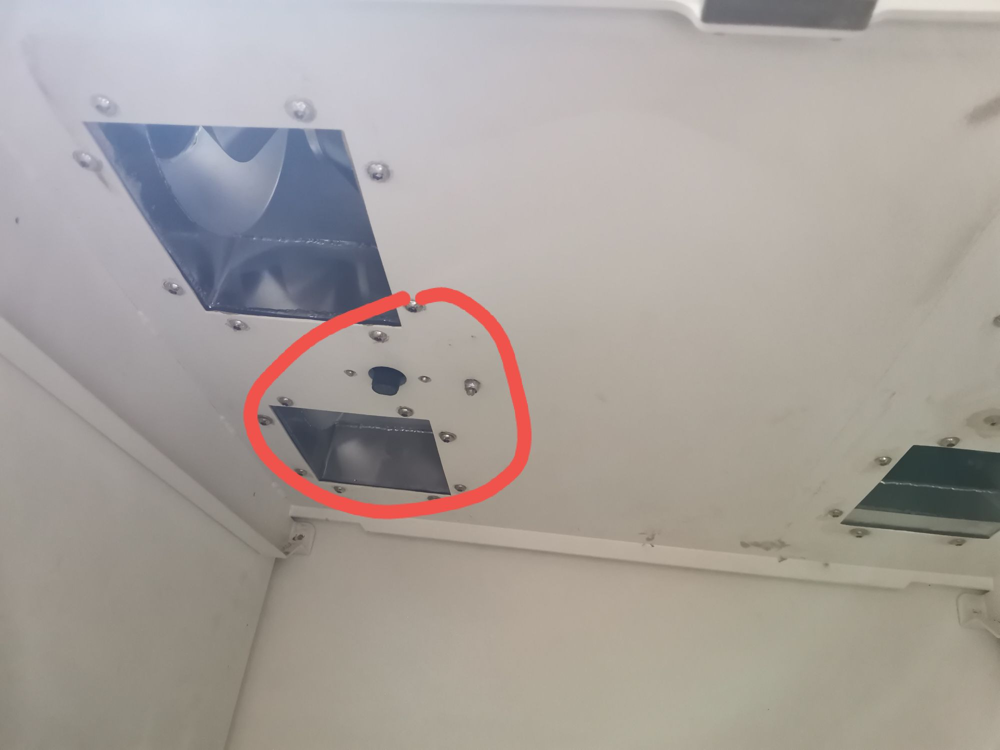
Wipe the sensor clean — the sensor is located above the large dust bin. Restart the machine after cleaning.
3
With the machine OFF and unplugged, reconnect any disconnected sensor or remote receiver wires.
4
If none of the above resolve the issue, proceed to the sensor test and wiring checks below.
Sensor Function Test

To determine whether the sensor is working correctly:
1
Turn the machine ON to Standby mode — screen blinking, motor not running.
2
Remove the dust bin and place your hand directly below the sensor.
3
Move your hand up — the alarm should only trigger when your hand is close to the sensor. If the alarm triggers when your hand is midway or lower, the sensor is faulty. If it triggers only near the sensor, the sensor likely just needs a thorough cleaning.
If thorough cleaning and restarting does not clear Err15, proceed to check the wiring connections next.
Dust Bin Sensor Location
Sensor Location Fig. 1
Dust bin sensor location
Sensor Detail Fig. 2
Dust bin sensor detail
Checking the Wiring Connections
1
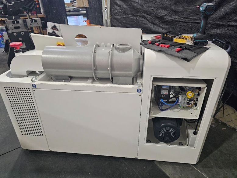
Machine OFF and unplugged. Remove the rear switch panel. Then remove the electrical box panel — the power switch must be in the OFF position to pull the panel free.
2
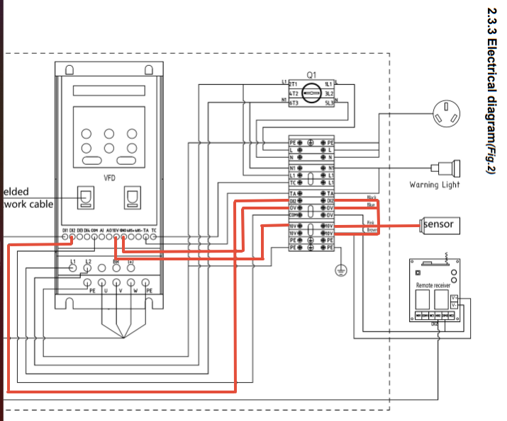
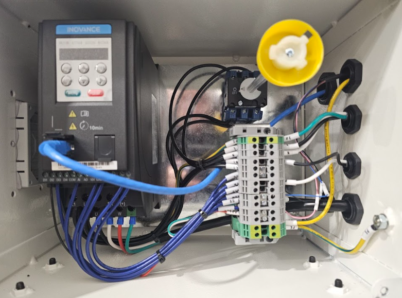
On the terminal block — right side, check that the wires connected to terminals 3, 4, 6, and 7 (counting up from the bottom) are secure. These are the dust bin sensor connectors.
3
On the terminal block — left side, check that the wires connected to terminals 4, 6, and 7 (counting up from the bottom left) are secure. These run to the VFD's D|2, 10V, and 0V/Ground terminals.
4
If all terminal block connections appear tight, remove the metal encasement between the separators and check that the connections at the sensor itself are not loose.
Electrical Box & Wiring Reference
Electrical Box — Panel Removal & Access Fig. 3
G-700 electrical box panel removal
Terminal Block — Sensor Wiring to Terminal Block & VFD (View 1) Fig. 4
Terminal block sensor wiring diagram view 1
Terminal Block — Sensor Wiring to Terminal Block & VFD (View 2) Fig. 5
Terminal block sensor wiring diagram view 2
Last Resort — Disconnect the DI2 (Digital Input #2) Communication Wire
Use with Caution — Last Resort Only

Disconnecting the sensor removes the automatic dust bin full protection. This is only recommended for specific situations where the benefits outweigh the risk of overfilling the bins and filters — for example, with high-static materials such as PVC dust that frequently adhere to the sensor and trigger false alarms.

If the issue persists after all prior steps, disconnect the sensor's DI2 communication wire from terminal DI2. Wrap the exposed wire end securely with electrical tape and/or a wire cap, then test the machine to confirm it starts and runs without triggering an external fault.

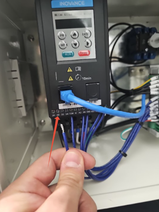
DI2 Wire — Wiring Diagram Fig. 6
D2 communication wire disconnect location
DI2 Wire — LocatioN Fig. 7
D2 wire capped and taped
i

If the issue persists after all troubleshooting steps, please contact our support team for further assistance.

Was this article helpful?

That’s Great!

Thank you for your feedback

Sorry! We couldn't be helpful

Thank you for your feedback

Let us know how can we improve this article!

Select at least one of the reasons
CAPTCHA verification is required.

Feedback sent

We appreciate your effort and will try to fix the article