Alpha HW615/Ambassador C14 Band Saws: Upper and Lower Flywheel Removal

Created by Gabriel Izzo, Modified on Fri, 15 May at 3:22 PM by Gabriel Izzo

Band Saw · Maintenance
Upper & Lower Flywheel Removal — Belt Replacement & Tensioning

Complete instructions for upper flywheel removal and reinstallation, lower flywheel removal, motor belt replacement, and belt tensioning for the Alpha HW615 and Ambassador C14 band saws. The process is identical for both models.
Alpha HW615
Ambassador C14
Warning — Moving Parts Hazard
Risk of serious injury — read all safety instructions before proceeding
+
Disconnect the machine completely from the power source before performing any maintenance or removing any components.
+
Wait for all moving parts to come to a complete stop before opening any covers or accessing internal components.
+
Use appropriate tools only. Do not use excessive force when loosening or tightening fasteners as this may damage components.
+
Re-check blade tension and tracking before returning the machine to operation after any flywheel or belt service.
i
If you are not comfortable performing this maintenance, consult a qualified service technician before proceeding.
Tools Required
Metric Hex Key Set or Metric T-Handle Set
18mm Open-End Wrench Socket Wrench / Socket Set
Part 1 — Upper Flywheel Removal & Reinstallation
1
Remove the saw blade.
2
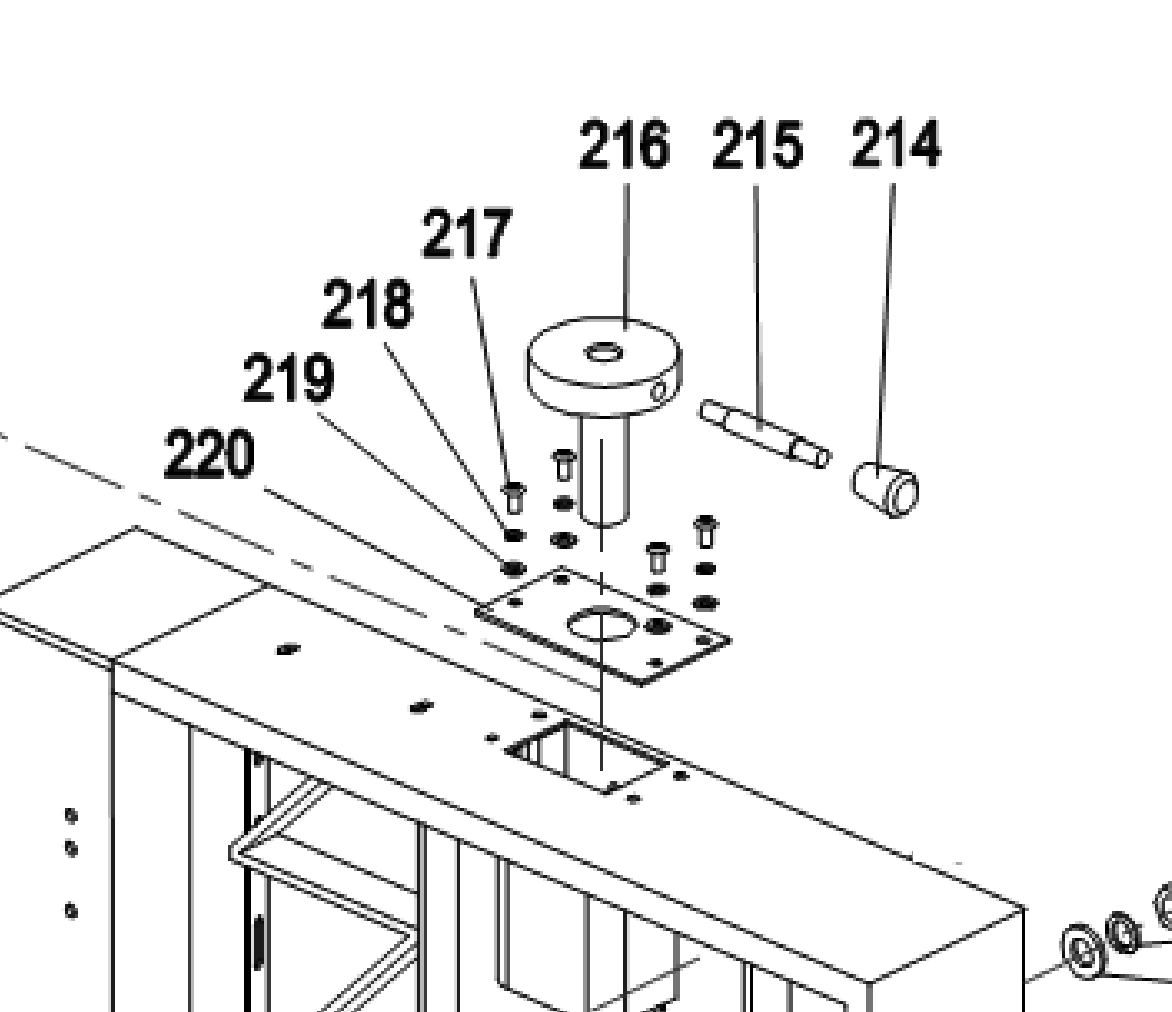
Remove the lifting rod
A
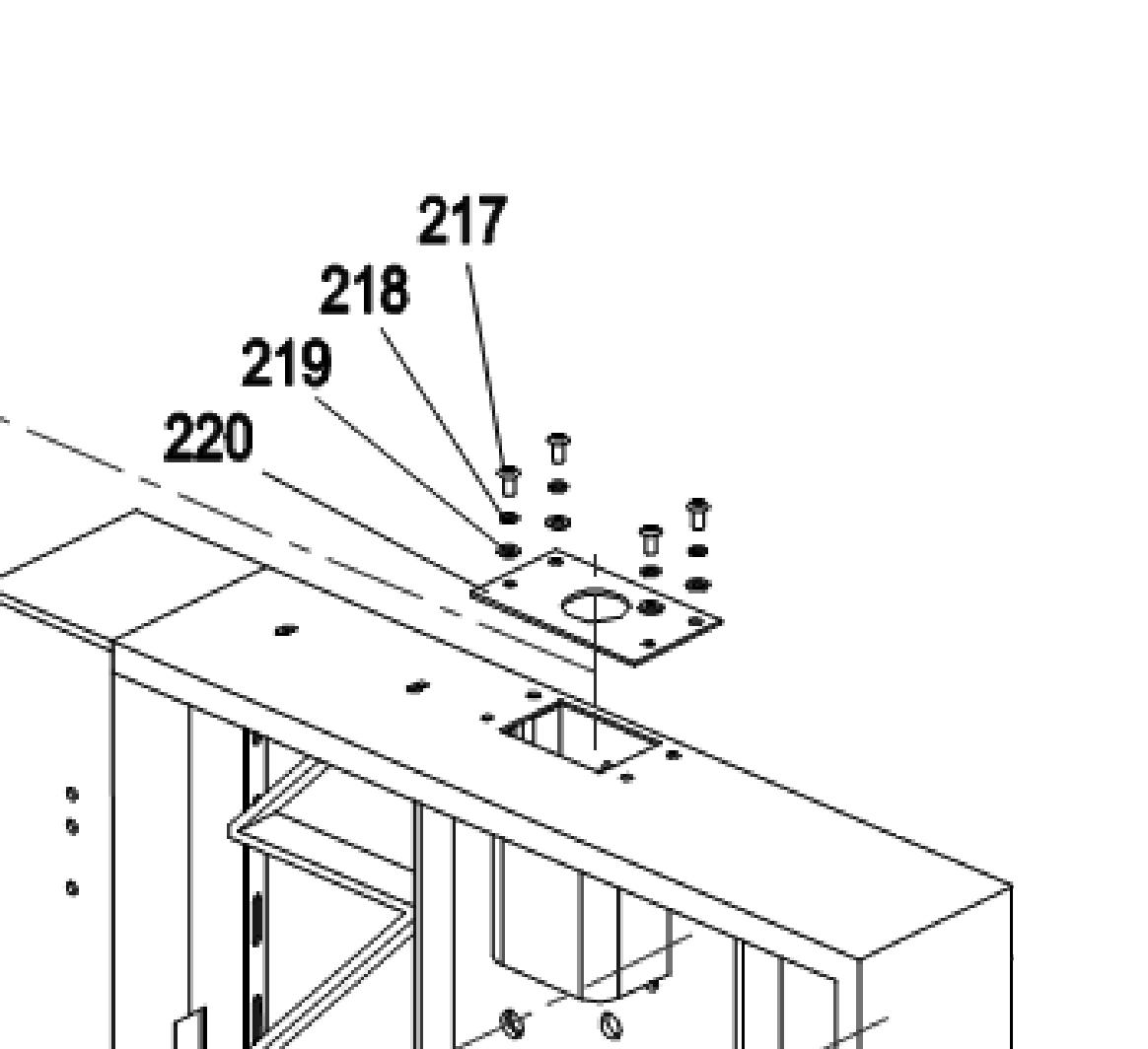
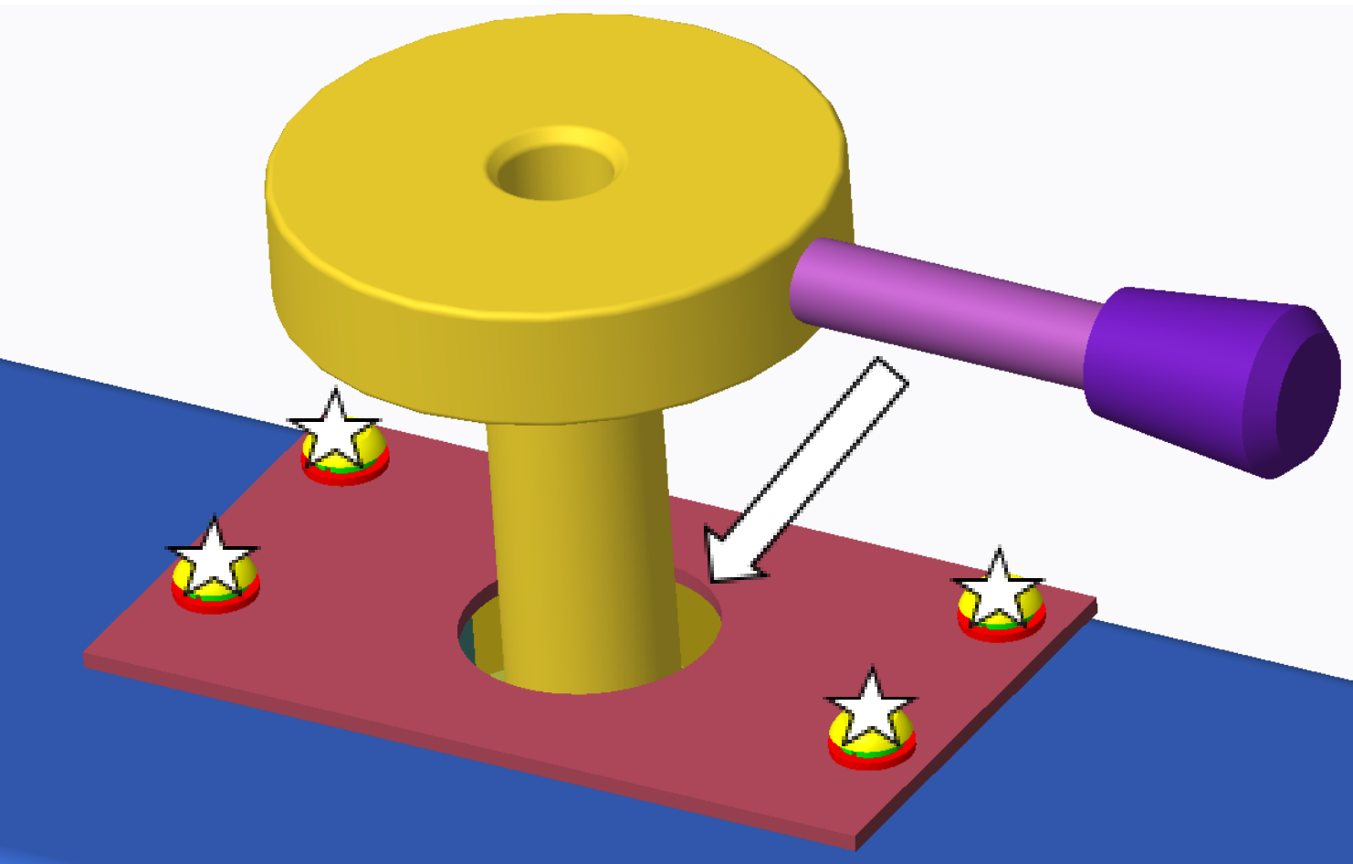
Using the supplied 3mm Allen key, remove the four locking screws of the top plate.
Step 2A — Top Plate Locking Screws Fig. 1
Step 2A — Top Plate Locking Screws
B
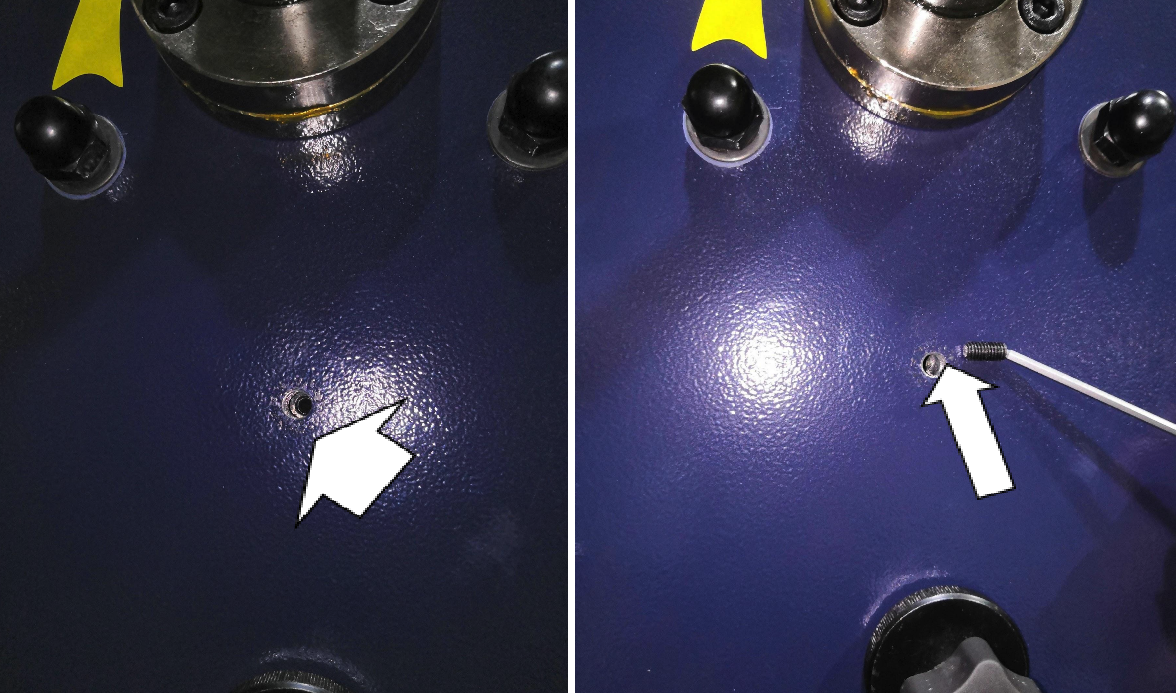
Using the supplied 5mm Allen wrench, remove the M8 screw on the back of the upper box.
Step 2B — M8 Screw, Back of Upper Box Fig. 2
Step 2B — M8 Screw, Back of Upper Box
C
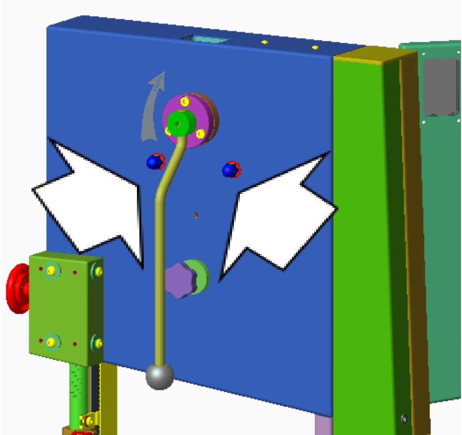
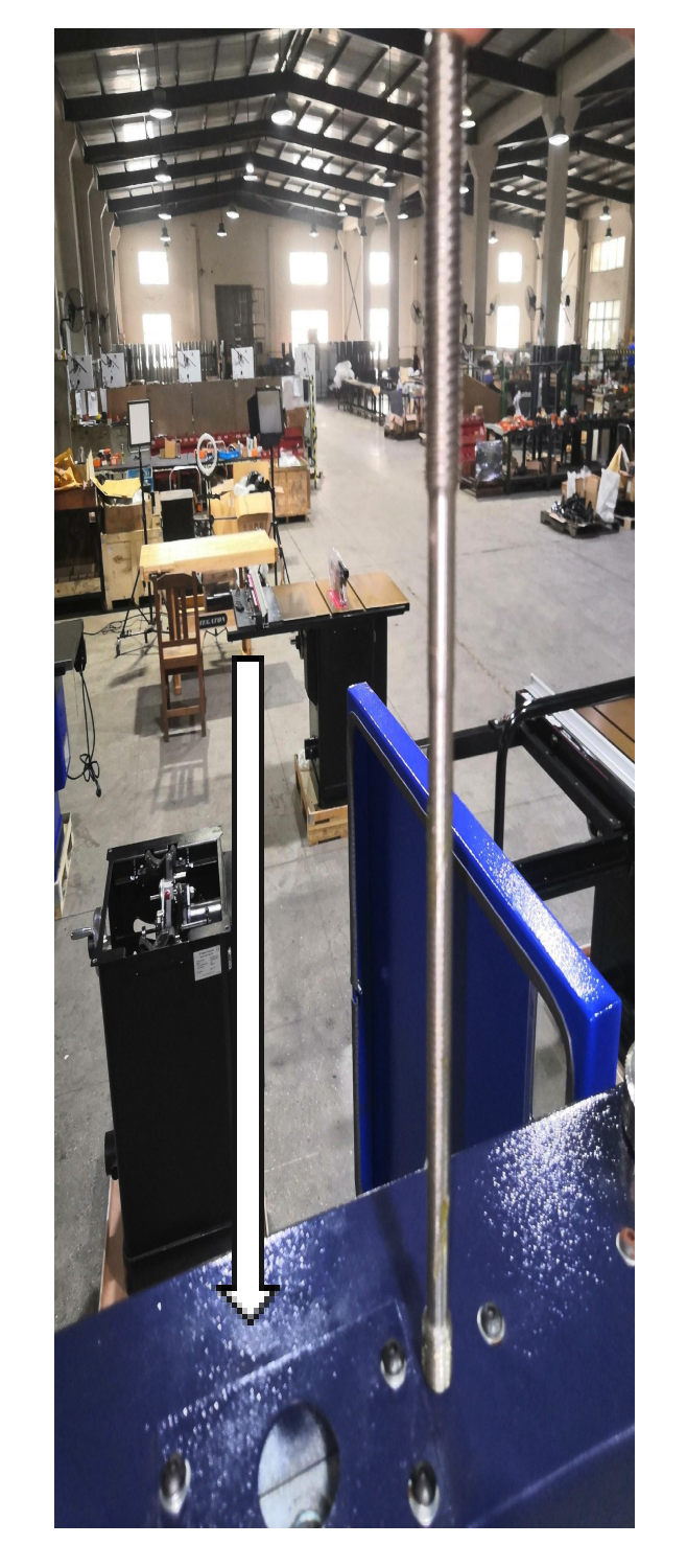
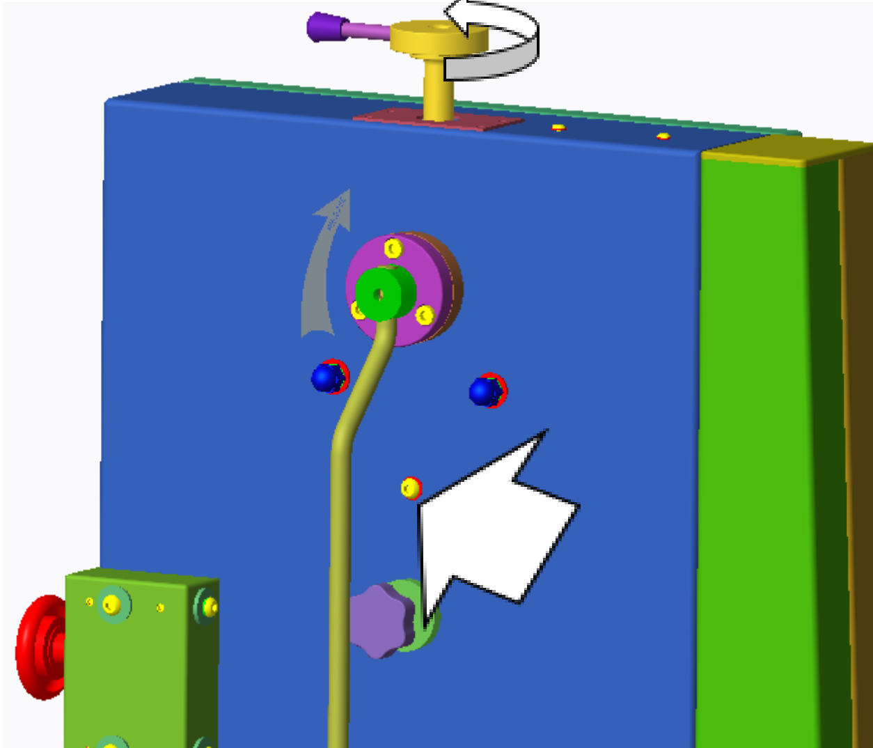
Rotate the top adjustment handle to drive the upper wheel assembly downward until the lifting rod locking screw comes out of the M8 screw hole. Remove the lifting rod locking screw using the 3mm Allen wrench.
Note: If the adjustment handle is rotated and removed before the lifting rod locking screw comes out, use a suitable tool to directly rotate the lifting rod instead.
Step 2C — Lifting Rod Locking ScrewFig. 3
Step 2C — Lifting Rod Locking Screw
D
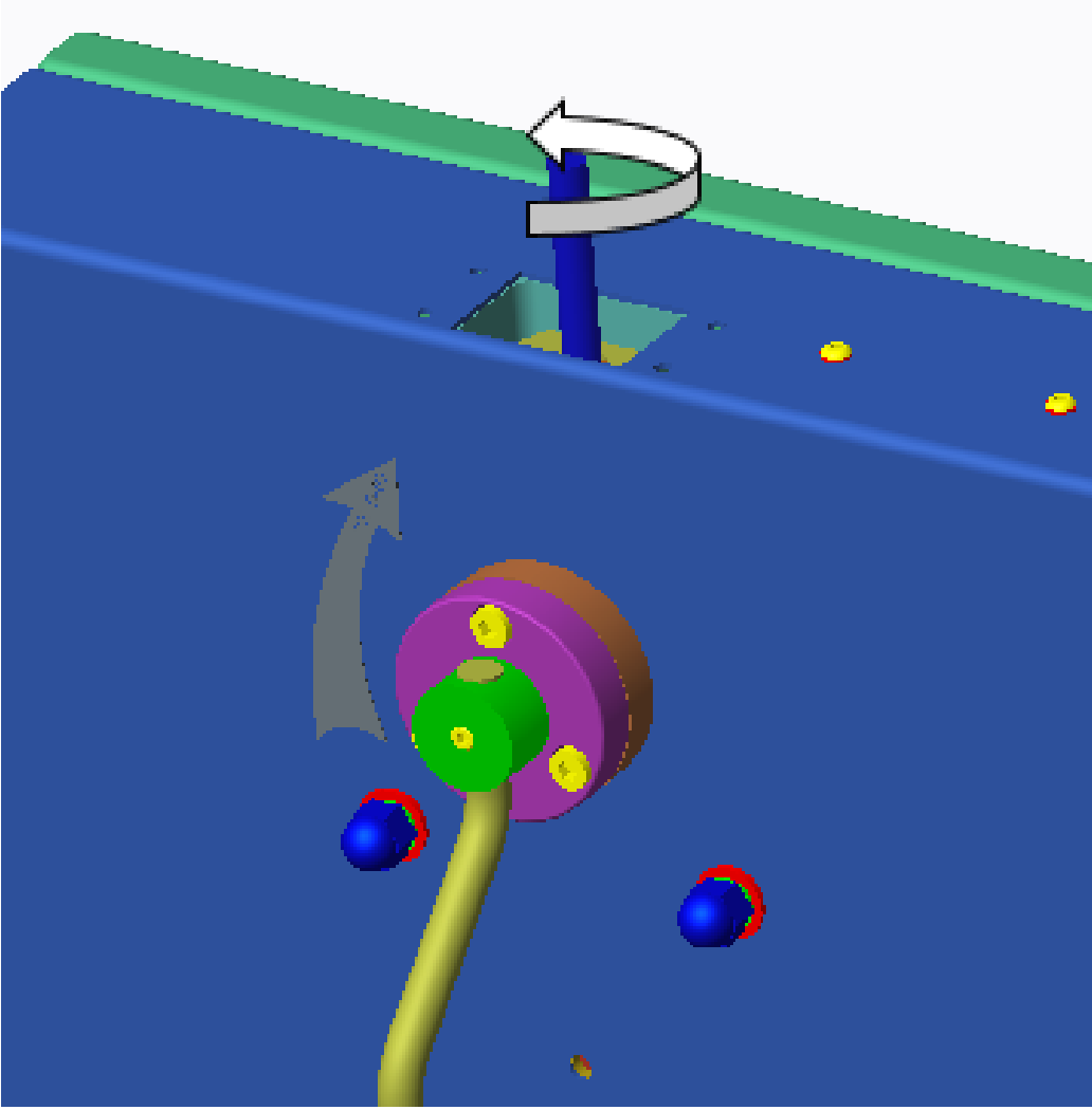
Rotate to remove the adjusting handle. Remove the top plate. Rotate to remove the lifting rod.
Step 2D — Lifting Rod Removal Fig. 5
Step 2D — Lifting Rod Removal
3
Remove the upper wheel assembly
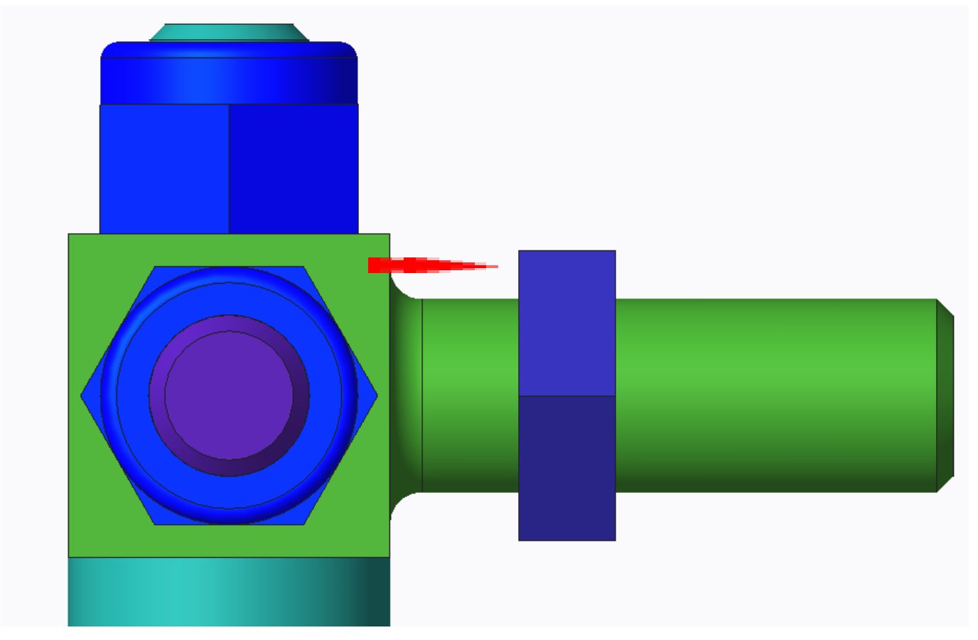
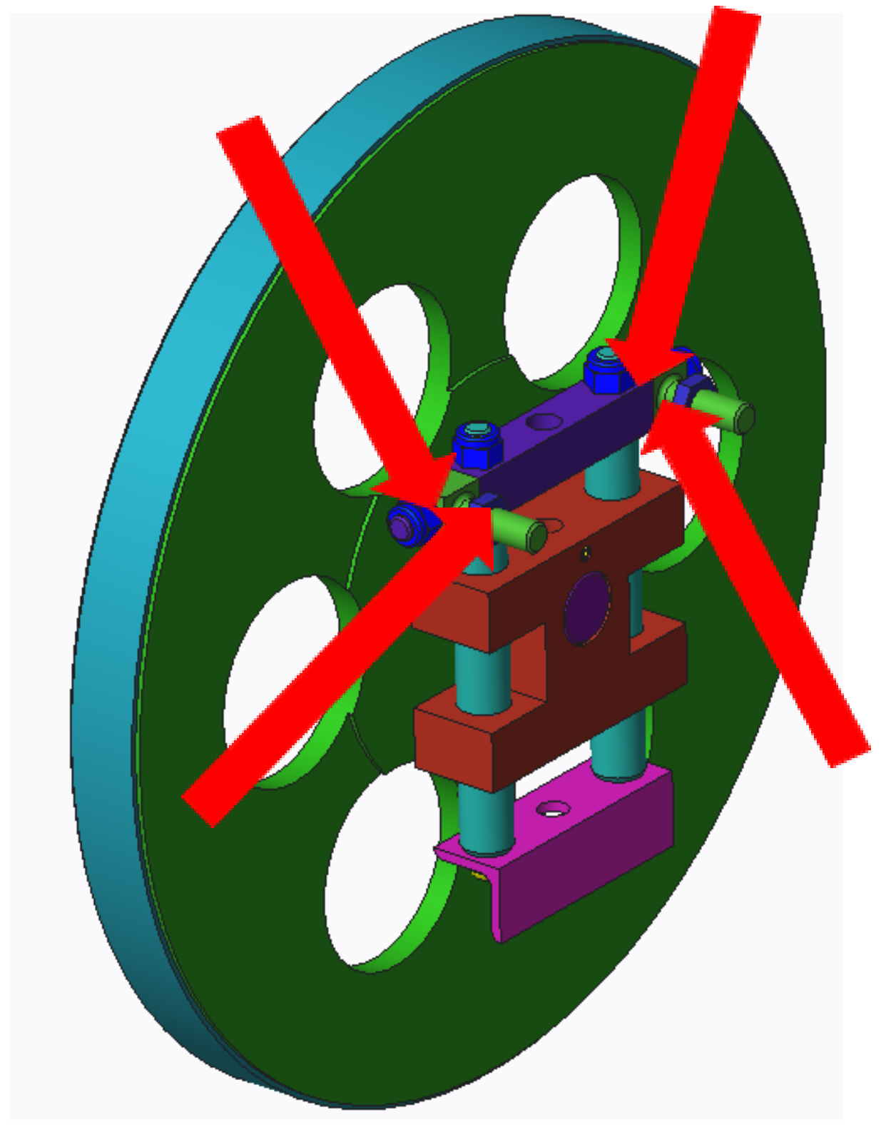
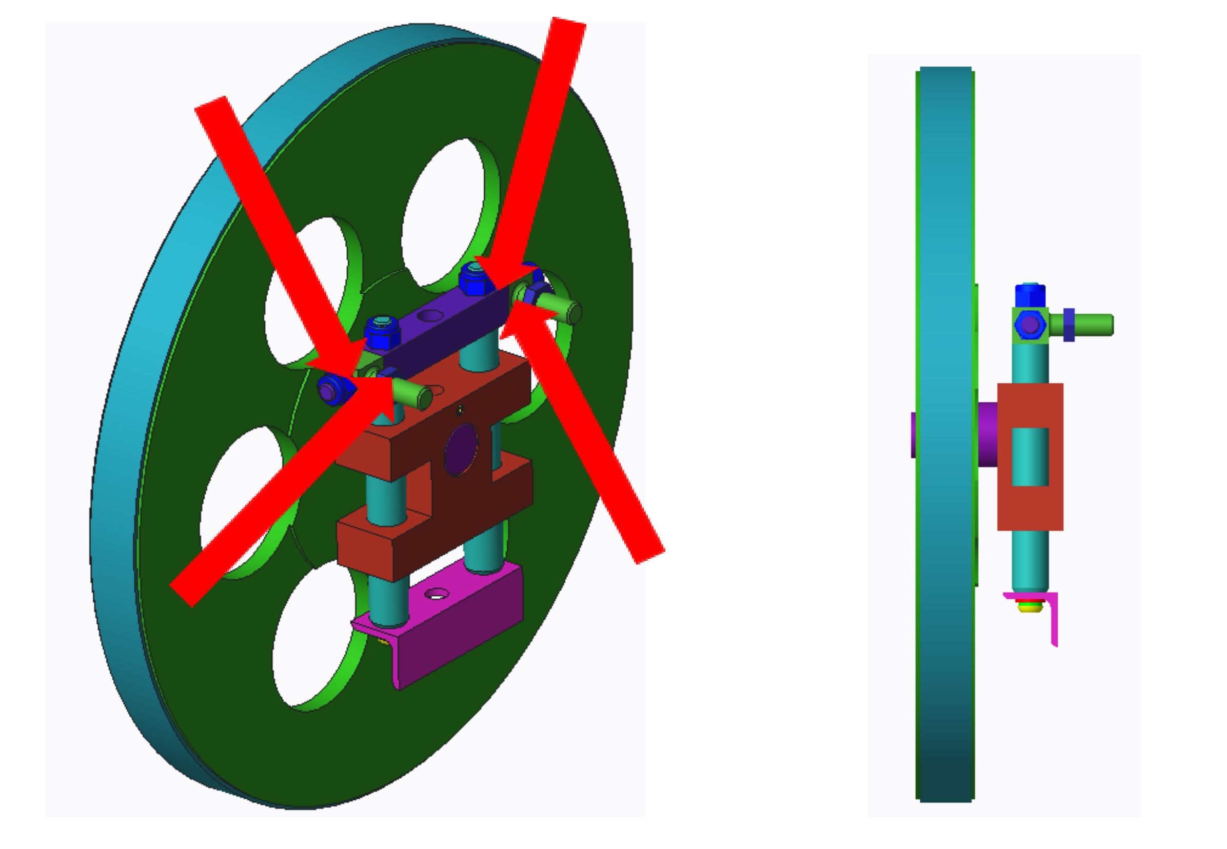
Using an 18mm open-end wrench, remove the two cap nuts that fix the upper wheel assembly.
Critical: After removing the upper wheel assembly, measure and record the distance between the square screws on both sides and the M12 thin nut. These two dimensions are required for correct reinstallation.
Step 3 — Cap Nut & M12 Measurement (Left) Fig. 6
Step 3 — Cap Nut & M12 Measurement (Left)
Step 3 — Cap Nut & M12 Measurement (Right) Fig. 7
Step 3 — Cap Nut & M12 Measurement (Right)
4
Install the new upper wheel assembly
Screw the two M12 thin nuts into the square screws at the exact distances recorded in Step 3 — the spacing must match the removed assembly. Reset the upper wheel assembly, install it on the frame, and lock the cap nuts.
Step 4 — New Upper Wheel Assembly Installation Fig. 8
Step 4 — New Upper Wheel Assembly Installation
5
Install the lifting rod and return the tension pointer
A
Screw the lifting rod into the threaded hole, ensuring the short part of the thread faces downward. Install the lifting rod fixing screw and the process hole screws.
Step 5A — Lifting Rod Installation Fig. 9
Step 5A — Lifting Rod Installation
B
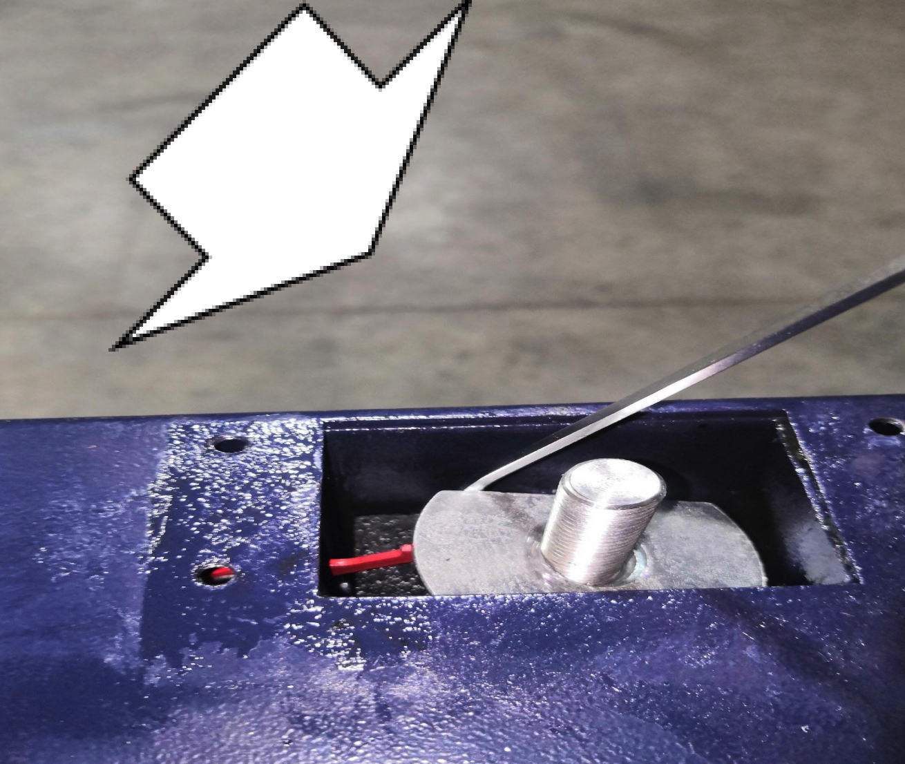
Return the tension pointer to its position. Use an Allen wrench to hook up the tension pointer pressing piece and place the tightening pointer under the pressing piece.
Step 5B — Tension Pointer Positioning Fig. 10
Step 5B — Tension Pointer Positioning
Step 5B — Tension Pointer Seated Fig. 11
Step 5B — Tension Pointer Seated
C
Install the top plate, then install the adjustment handle.
Step 5C — Top Plate Installation Fig. 12
Step 5C — Top Plate Installation
Step 5C — Adjustment Handle Installation Fig. 13
Step 5C — Adjustment Handle Installation
Debug the upper wheel assembly
Adjust the deviation nut so the saw blade sits in the proper center position on the wheel. Refer to the instruction manual for detailed tracking adjustment guidance.
Step 6 — Upper Wheel Tracking Adjustment Fig. 14
Step 6 — Upper Wheel Tracking Adjustment
Part 2 — Lower Flywheel Removal, Belt Replacement & Tensioning

The lower flywheel removal process is identical to the motor belt replacement procedure. Refer to Fig. 16 (Manual §6.5, page 18) for component locations A, B, and C.
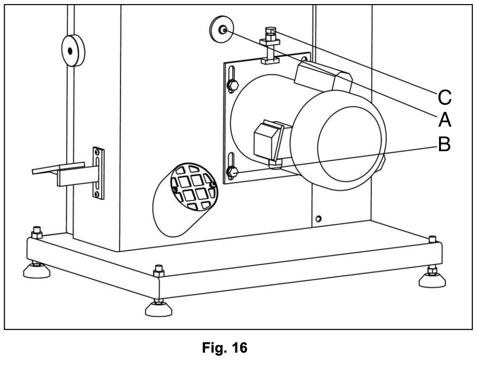
Fig. 16 Reference: Lower wheel locking screw Motor bracket mounting bolts Belt tension adjustment bolt
Fig. 16 — Belt Tension & Lower Flywheel Reference
Fig. 16 showing motor bracket components A, B and C
1
Disconnect the machine from the power source.
2
Remove the blade.
3
Loosen the four motor bracket mounting bolts (B) and loosen the belt tension adjustment bolt (C).
4
Lift the motor and re-tighten bolts (B) to hold the motor in the raised position.
5
Remove the lower wheel locking screw (A) on the back of the frame and remove the lower wheel.
6
Remove the old belt and install the new one on the wheel belt pulley, making sure it seats properly in the pulley grooves.
7
Slide the wheel back to the frame and tighten wheel locking bolt (A). Then mount the belt on the motor pulley.
8
Loosen motor bracket mounting bolts (B) and allow the motor to lower.
9
The weight of the motor should generally produce the proper belt tension. Check by pushing with moderate pressure against the center of the belt.
A correctly tensioned belt will deflect approximately 1/2". If tension is insufficient, push down on the motor by tightening belt tension bolt (C).
10
Re-tighten motor bracket mounting bolts (B) and belt tension bolt (C).
Re-check blade tension and tracking before operating the saw.
Video Walkthrough

The video below demonstrates lower wheel removal, belt re-installation, and belt tensioning.

Band Saw Belt Replacement Video
Lower wheel removal  ·  belt re-installation  ·  tensioning
 
i

The C14 and HW615 band saw flywheel removal processes are identical. If you need further assistance after following these steps, please contact our support team.

Was this article helpful?

That’s Great!

Thank you for your feedback

Sorry! We couldn't be helpful

Thank you for your feedback

Let us know how can we improve this article!

Select at least one of the reasons
CAPTCHA verification is required.

Feedback sent

We appreciate your effort and will try to fix the article